TM 5-4210-233-14&P-2
6-65. AIR COMPRESSOR-Continued
(14) Coat rod bearings with engine oil (Item 10,
(15) Lubricate the cylinder walls and pistons.
(16) Remove rod cap and bearing from connecting rod.
Stagger ring gaps by 120 degrees. Using ring
compressor, insert piston so that top of piston is
flush with top of the block.
(17) Turn assembly over and position connecting rod
on crankshaft journal making sure bearing inserts
are in place. Lubricate rod journal with engine oil
(Item 10, Appendix E).
(18) Install connecting rod bearing caps and inserts
aligning arrows on bearing caps and rods. Install
connecting rod bolts; tighten bolts with 5/16" 12
point heads to 185 to 225 in. Ibs. (21 to 25 Nm),
tighten bolts with " 12 point heads to 105 to
135 in. Ibs. (12 to 15 Nm).
CAUTION
Do not overtighten bolts.
(19) Assemble the second rod using same procedure.
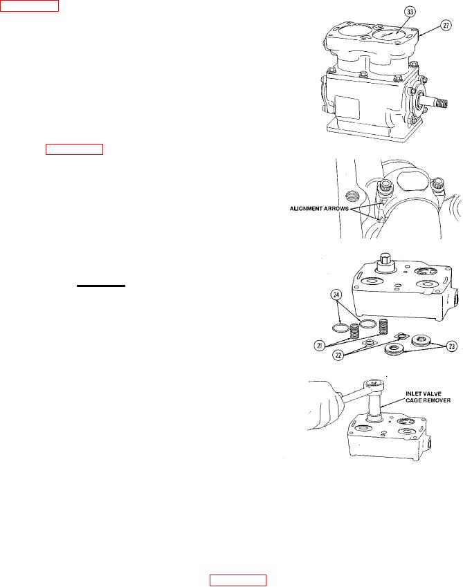
20) Replace the bottom plate. Tighten the six hex
head bolts 110 to 150 in. lbs. (13 to 17 Nm).
(21) Invert cylinder head and insert new copper
washers (19 and 24) into all four valve ports.
(22) Insert exhaust valve spring (18), exhaust valves
(17) and exhaust valve seats (16). Using a 9/16"
Allen wrench tighten valve seats to 70 to 90 ft. lbs.
(95 to 122 Nm).
23) Insert inlet valve seat (23), inlet valve (22), inlet
valve springs (21), and inlet valve cages (20).
NOTE
The inlet valve and inlet valve springs must be centered to
insure the valve is not torqued between the valve seat and valve
cage. Torque the inlet valve cages to 70 to 80 ft. Ibs. (95 to
108 kPa) using remover tool (Appendix B, Section III, Item 95).
6-395

