TM 5-4210-233-14&P-2
6-65. AIR COMPRESSOR-Continued
(24)
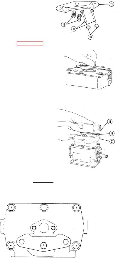
Turn head over to insert unloader springs (12).
(25)
Install springs (12) and new O-rings (10) on
unloader pins (11).
(26)
Apply silicone grease (item 11, Appendix E)
to O-rings.
(27)
Insert assembled unloader pins into head.
(28)
Place new unloader gasket (13) on unloader
cover. Assemble these two items to head as
a unit compressing unloader springs; hold
firmly until unloader cover bolts (7) and washers
are installed.
(29)
Tighten these bolts to approximately 10 in. Ibs.
(1 Nm). These bolts will be tightened to final
torque after head bolts are torqued.
(30)
Place new head to block gasket (15) on cylinder
block (27). Place head (14) on gasket assembling
six head bolts. One long head bolt is to be
inserted through unloader cover plate. Tighten
head bolts to 18 to 22 it. Ibs. (25 to 29 Nm) in
proper sequence. Retighten head bolts to 27 to
33 ft. Ibs. (37 to 44 Nm) in same sequence.
CAUTION
Do not overtighten bolts.
6-396

