
TM 5-4210-233-14&P-2
6-65. AIR COMPRESSOR - Continued
b.
Cleaning and Inspection.
CAUTION
Do not use solvents containing chemicals injurious to aluminum alloy. Never use
gasoline, fuel oil or kerosene as a cleaning solvent.
WARNING
Dry cleaning solvent P-D-680 is potentially dangerous. Avoid repeated and
prolonged breathing of vapors and skin contact with the liquid. Do not use near
open flame, arcing equipment or other ignition sources. Always wear eye
protection and protective clothing. The flash point of P-D-680 is 100 to 138 deg. F
(38 to 59 deg. C).
(1) Wash all parts in cleaning solvent (Item 3, Appendix E). Blow dry with compressed air.
CAUTION
Be extremely careful to avoid scratching machined surfaces.
(2) Clean carbon deposits from cylinder head's (14) interior surfaces. Clean all interior air and water
passageways.
(3) Remove carbon from piston (33) crowns and ring grooves.
(4) Blow out all drilled passageways with compressed air to insure they are open.
(5) Remove old gasket material sealer from gasket surface
(6) Examine cylinder head (1 4) for cracks and damaged
threads. Head gasket surface must be free of nicks and
gouges. Replace head if damaged.
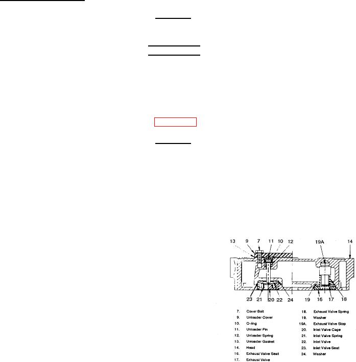
(7) Inspect inlet (22) and exhaust valve (17) disc for wear.
Replace valves if cracked, pitted or grooved on either
side.
(8) Check inlet (21) and exhaust valve (18) springs for loads
at specified heights. Inlet valve spring load should be .36
to .62 Ibs (.16 to .28 kg) at .287 in. (7.29 mm). Exhaust
valve spring load should be 3.30to 3.70 Ibs (1.50 to 1.68
kg) at .73 in. (18.5 mm).
(9) Examine inlet valve cages (20) for damage and wear. Measure valve guide diameter and distance from
top of cage to valve stop. Examine inlet valve seat (23) for damage. Measure from valve seating
surface to surface that contacts valve cage. Inlet valve guide diameter should be .916 to .920 in. (23.27
to 23.37 mm). Top of inlet valve cage to valve stop should be .131. to 137 in. (3.33 to 3.48 mm). Valve
seating surface to valve cage contact surface should be .0235 to .0265 in. (.5969 to .6731 mm).
6-389