DRAFT
TM 5-4210-249-13&P-4
0606
- - - - - - - - - - - - - - - - - - - - - - - - - - - - - - - - - - - - - -
TFFT00638
NOTE
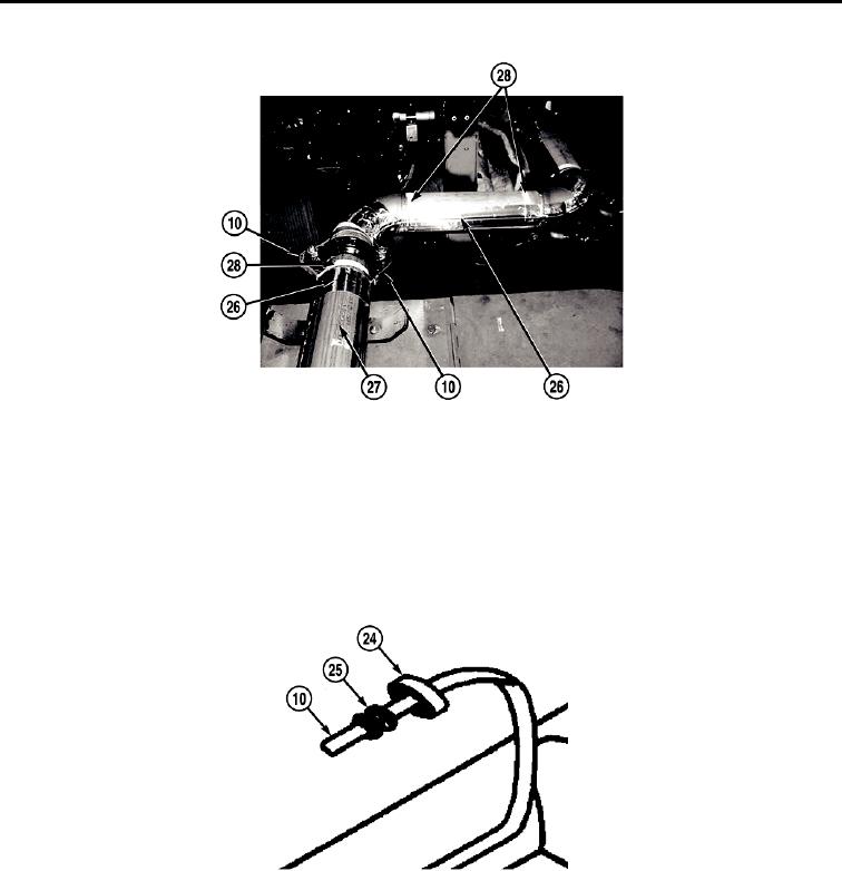
Perform Steps (8) and (9) to install heat trace cable on pipe. Allow extra heat trace cable
for connecting to splice connectors.
8.
Install heat trace cable (10) on both sides of pipe (27) with glass tape (28).
9.
Install aluminum tape (26) over heat trace cable (10) and pipe (27).
- - - - - - - - - - - - - - - - - - - - - - - - - - - - - - - - - - - - - -
TFFT00962
NOTE
Perform Steps (10) through (30) to install heat trace cable to splice connectors.
10. Slide pressure plate (24) and grommet (25) on heat trace cable (10).
0606-8

