DRAFT
TM 5-4210-249-13&P-4
0606
- - - - - - - - - - - - - - - - - - - - - - - - - - - - - - - - - - - - -
TFFT00969
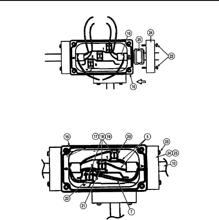
25. Install heat trace cable (10) and grommet (25) in splice connector body (16).
26. Seat grommet (25) in splice connector body (16).
27. Install pressure plate (24) on splice connector body (16) with two screws (23).
- - - - - - - - - - - - - - - - - - - - - - - - - - - - - - - - - - - - -
TFFT00961
NOTE
Trim all extra lengths of wire and any loose braid after installing wires in splice connector
body.
28. Install one heat trace cable bus wire (5) on block (20) with clamp (19), lockwasher (18), and screw (17).
29. Install one heat trace cable bus wire (5) on block (21) with clamp (19), lockwasher (18), and screw (17).
30. Install heat trace braid (7) on block (22) with clamp (19), lockwasher (18), and screw (17).
31. Install bottom cover (15), two gaskets (14), and top cover (13) on splice connector body (16) with four
screws (11).
0606-11

