DRAFT
TM 5-4210-249-13&P-4
0606
- - - - - - - - - - - - - - - - - - - - - - - - - - - - - - - - - - - - - -
TFFT00959
6.
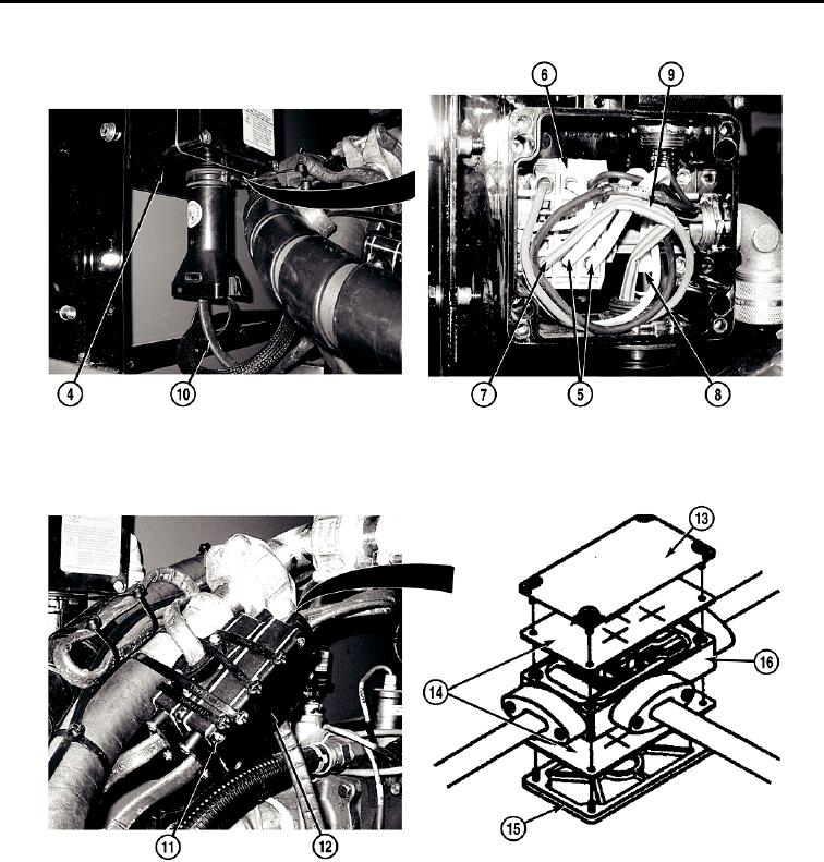
Remove heat trace cable (10) from bottom of junction box (4).
- - - - - - - - - - - - - - - - - - - - - - - - - - - - - - - - - - - - - -
TFFT00960
NOTE
Perform Steps (7) through (13) to remove other end of heat trace cable from splice
connector.
Remove required insulation to access heat trace cable to be replaced.
7.
Remove four screws (11) from splice connector (12).
8.
Remove top cover (13), two gaskets (14), and bottom cover (15) from splice connector body (16).
0606-4

