TM 5-4210-233-14&P-2
6-13. CYLINDER HEAD REMOVAL/INSTALLATION - Continued
NOTE
Fuel rod is removed through cylinder head. Left
and right bank fuel rods are removed differently.
Step (8) covers left bank and step (9) covers
right bank.
(8)
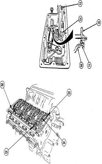
Lift connecting pin (1 9) 3/4-in.
(19 mm) and remove left bank fuel
rod (20) from control link operating
lever (21).
(9)
Remove screw (22) and right bank
fuel rod (23) from control link
operating lever (21).
(10)
Tag eight fuel tubes (24), loosen sixteen fuel tube nuts (25), and remove eight fuel tubes.
NOTE
Checking tightness of cylinder head screws may show cause of cylinder head failure.
(11)
Check and record tightness on 10 cylinder head screws (26). Tightness must be between 230 to
240 lb-ft (312 to 325 N.m).
6-79

