TM 5-4210-233-14&P-2
6-13. CYLINDER HEAD REMOVAL/INSTALLATION - Continued
NOTE
Leave in two screws to right and left of head.
(12)
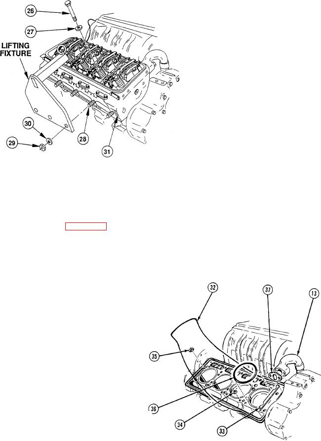
Remove eight screws (26) and washers (27).
(13)
Install lifting fixture (Appendix B, Section III, Item 22) over three studs (28).
(14)
Secure with three nuts (29) and washers (30).
(15)
Remove two remaining
screws (26) and washers (27).
(16)
Using a suitable lifting device
lift cylinder head (31).
NOTE
Compression gaskets are color coded.
Be sure to note color for replacement.
(17)
Remove seal strip gasket
(32), two support shims (33),
sixteen water seals (34), oil
seal (35), and four
compression gaskets (36).
(18)
Remove gasket (37) from
crossover tube (1 3).
6-80

