
TM 5-4210-233-14&P-2
6-28. SYNCHRONOUS AND TIMING REFERE NCE SENSOR - Continued
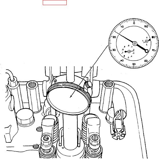
(8) Turn the crankshaft slowly, in the direction of rotation, until the dial indicator pointer reads exactly
1.216" (30.89 mm) of piston travel.
NOTE
At this point, the teeth on the rear of the pulse wheel, located on
the rear of the cam pulley, are in the proper location for
positioning the sensors. The sensor bracket must be positioned
correctly in relation to the engine front end plate. Use SRS/TRS
timing tool (Appendix B, Section III, Item 40) to accomplish this
task.
(9) Tap the end of the camshaft pulley with a fiber mallet or rubber hammer to take up the camshaft
end play.
6-138