
TM 5-4210-233-14&P-2
6-28. SYNCHRONOUS AND TIMING REFERENCE SENSOR - Contlnued
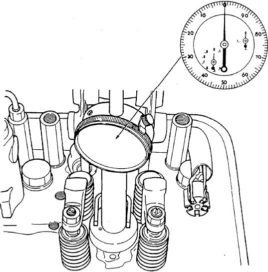
(3) Insert dial indicator tool into the injector bore, install injector hold-down crab and tighten the bolt.
(4) Turn the crankshaft slowly in the direction of rotation and note indicator movement. Stop turning
when the dial hand just stops.
(5) Turn the crankshaft slowly, opposite the direction of rotation, until the dial indicator hand just starts to
move. The piston is now at top-dead-center.
(6) Before piston downward travel can be measured, the dial indicator must be "zeroed". Loosen the
clamp screw and remove the slotted spacer. Lower the dial indicator until the two smaller indicator
hands are at "O" and the large hand is near "O".
(7) Tighten the clamp screw and zero the large hand by turning the outer ring of the dial face. Tighten
the bezel screw so the outer ring will not turn.
6-137