DRAFT
TM 5-4210-249-13&P-3
0320
- - - - - - - - - - - - - - - - - - - - - - - - - - - - - - - - - - - - -
TFFT02025
NOTE
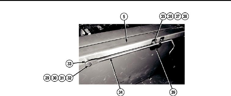
Both support rods and support rod hold-downs are replaced the same way.
10. Remove nut (29), lockwasher (30), two washers (31), and screw (32) from pump operator's panel housing (5).
Discard lockwasher.
11. Remove nut (33) and support rod (34) from screw (32).
12. Remove two nuts (35), lockwashers (36), washers (37), and screws (38) and support rod catch (39) from
pump operator's panel housing (5). Discard lockwashers.
END OF TASK
INSTALLATION
1.
Install support rod catch (39) on pump operator's panel housing (5) with two screws (38), washers (37),
lockwashers (36), and nuts (35).
2.
Install support rod (34) on screw (32) with nut (33).
3.
Install screw (32) on pump operator's panel housing (5) with two washers (31), lockwasher (30), and nut (29).
4.
Install three seals (28) on pump operator's panel cover A (9).
5.
Install two seals (27) on pump operator's panel cover B (18).
6.
Install handle (26) on pump operator's panel cover B (18) with four screws (25), washers (24), and
locknuts (23).
NOTE
Both rubber hold-downs are installed the same way.
7.
Install rubber hold-down (22) on pump operator's panel cover B (18) with screw (21), washer (20), and
locknut (19).
8.
Install hinge (13) and plate (17) on pump operator's panel cover B (18) with eight screws (16), washers (15),
and locknuts (14).
0320-3

