DRAFT
TM 5-4210-249-13&P-1
0105
MALFUNCTION
TEST OR INSPECTION
CORRECTIVE ACTION
TFFT02783
Step 17.
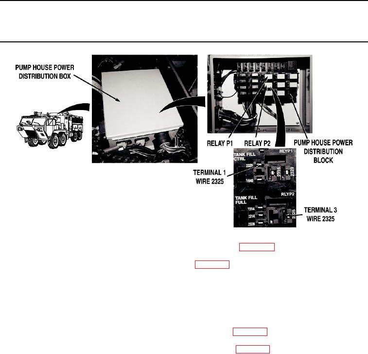
Turn battery disconnect switch to OFF Position (WP 0007). Remove relay
P2 (WP 0413). Install relay P3 in relay P2 connector location (WP 0413). Turn battery
disconnect switch to ON position (WP 0007). With a test lead set installed between
main wire harness wire 2328 (green) at auto fill controller connector, terminal A and a
known good ground. Check for 0 VDC between pump house power distribution wire
harness wire 2325 (black) at relay P1 connector, terminal 1 and a known good ground.
If 22 to 28 VDC are present, install relays in original positions and replace
relay P3 (WP 0413).
Step 18.
Turn battery disconnect switch to OFF position (WP 0007). Remove relay P3 from relay
P2 connector (WP 0413). Install relay P1 in relay P2 connector location (WP 0413)
Turn battery disconnect switch to ON position (WP 0007). With a test lead set installed
between main wire harness wire 2328 (green) at auto tank fill controller connector,
terminal A and a known good ground. Check for 0 VDC between pump house power
distribution wire harness wire 2325 (black) at relay P1 connector, terminal 1 and a
known good ground
a.
If 22 to 28 VDC are present, install relays in original positions and
replace relay P1 (WP 0413).
b.
If direct tank fill auto tank fill function does not operate properly, replace
auto tank fill controller (WP 0418).
0105-15

