
TM 5-4210-233-14&P-2
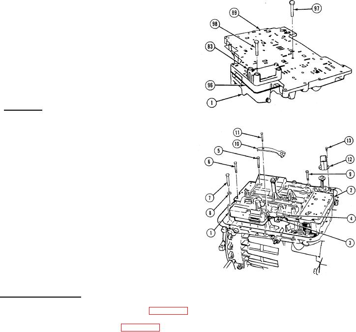
6-62. CONTROL VALVE BODY - Continued
(44)
Insert six screws (97) through oil transfer plate
(89), separator plate (96), and control valve
body (1) to align screw holes.
(45)
Place modulator valve body (83) on oil transfer
plate (89) and install three screws (98).
(46)
Tighten screws (98) to 108 to 132 Ib-in. (12 to
15 N.m).
(47)
Remove six screws (97).
e. Installation.
(1)
Install control valve body (1) and transfer plate
(2), making sure shift ( rack pin (3) engages
slot on selector valve (4).
(2)
Install three screws (5).
(3)
Install seven screws (6).
(4)
Install two screws (7) and washers (8).
(5)
Install 15 screws (9) in control valve body (1).
(6)
Install manual detent lever (10) and screw (11)
in control valve body (1).
(7)
Install oil baffle (12) and two screws (13).
(8)
screws
(5,
6,
7,
9,11,and13)to108to1321b-in.(12to15N.m).
f. Follow-on Maintenance.
(1)
Install lockup cutoff valve body (see para 6-64.).
(2)
Install modulator valve (see para 6-63.).
6-379