TM 5-4210-233-14&P-2
6-62. CONTROL VALVE BODY - Continued
(31)
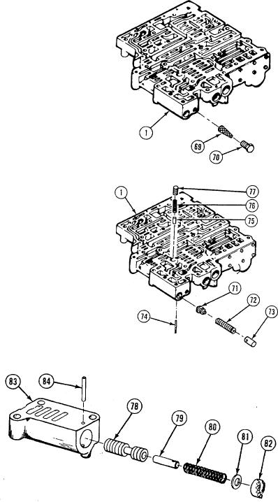
Install governor screen assembly (69) and plug (70) in control
valve body (1). Tighten plug to 50 to 60 Ib-in. (5.6 to 6.8
N.m).
(32)
Install accumulator valve (71), spring (72), and valve stop
(73) in control valve body (1).
(33)
Align pinhole in valve stop (73) with pinholes in control valve
body (1).
(34)
Press valve stop (73) and install retaining pin (74) in control
valve body (1).
(35)
Install valve stop (75), spring (76), and priority valve (77) in
control valve body (1).
(36)
Install modulator valve (78), valve stop (79), spring (80),
washer (81), and adjusting ring (82) in modulator valve body
(83).
(37)
Align pinhole in valve stop (79) with pinholes in modulator
valve body (83).
(38)
Press adjusting ring (82) and install retaining pin (84) in
modulator valve body (83).
6-377

