
TM 5-4210-233-14&P-2
6-32. PISTON, CONNECTING ROD AND LINER - Continued
(18)
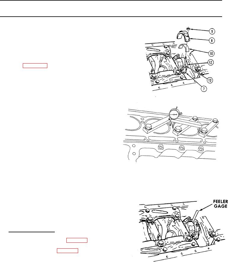
Seat connecting rod firmly on crankshaft journal (12).
(19)
Install cap (8) and bearing shell (10) over studs (13).
(20)
Install two nuts (9) and tighten to 60 to 70 Ib-ft (81 to
95 N.m).
(21)
Clamp the liner in place with hold-down clamp
(Appendix B, Section 111, Item 46) and tighten the two
bolts evenly.
(22)
Measure the distance from the top of the liner to the
top of the block with a dial indicator. The liner flange
must be .0418" to .0482" (1.062 to 1.22 mm) below
the surface of the block. However,
even though all of the liners are within
these specifications, there must not
be over .0015" (.038 mm) difference
between any two adjacent liners
when measured along the cylinder
longitudinal centerline. If the above
limits are not met, install a different
thickness insert, install the liner in
another cylinder bore and recheck, or
use a new cylinder liner.
(23)
Matchmark the liner and the cylinder
block with a felt pen so the liner may
be reinstalled in the same position in
the same block bore. Place the
matchmarks on the side opposite the
camshaft. Remove the hold-down
clamp and the cylinder liner. Do not
remove the liner insert.
(24)
Using feeler gauge, check that clearance between
each connecting rod attached to same crankshaft
journal is 0.008 to 0.01 6 in. (0.2 to 0.4 mm).
c.
Follow-on Maintenance.
(1) Install cylinder head (see para 6-13.).
(2) Install oil pump (see para 6-46.).
(3) Install oil pan (see para 5-27.).
(4) Remove engine from engine stand.
6-182