
DRAFT
TM 5-4210-249-13&P-3
FIELD LEVEL MAINTENANCE
FLOW SENSOR REPLACEMENT
INITIAL SETUP:
- - - - - - - - - - - - - - - - - - - - - - - - - - - - - - - - - - - - -
Tools and Special Tools
References
Standard Automotive Tool Set (SATS),
WP 0615, Fig. 113
(WP 0622, Item 25)
Equipment Conditions
Wrench, Pipe, 10"
Pump house panel A removed (WP 0540)
Tool Kit, General Mechanic's: Automotive
Water system drained (WP 0029)
(WP 0622, Item 27)
Materials/Parts
Oil, Lubricating (WP 0625, Item 37)
Preformed Packing (2)
REMOVAL
- - - - - - - - - - - - - - - - - - - - - - - - - - - - - - - - - - - - -
TFFT02521
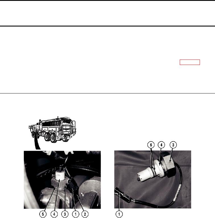
NOTE
All flow sensors are removed the same way. Flow sensor on No. 1 discharge valve (driver
side) shown.
1.
Disconnect flow sensor connector (1) from valve control wire harness connector (2).
2.
Loosen nut (3) and remove flow sensor (4) from adapter (5).
3.
Remove two preformed packings (6) from flow sensor (4). Discard preformed packing.
END OF TASK
0390-1