DRAFT
TM 5-4210-249-13&P-2
0223
- - - - - - - - - - - - - - - - - - - - - - - - - - - - - - - - - - - - - -
TFFT00622A
3.
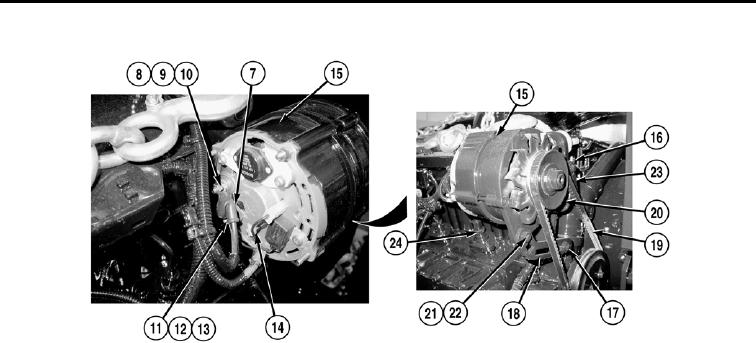
Pull rubber boot (7) back from stud (8).
NOTE
Tag and mark wires prior to removal to ensure proper installation.
4.
Remove nut (9) and wire (10) from stud (8).
5.
Remove nut (11) and wire (12) from stud (13).
6.
Disconnect connector (14) from alternator (15).
7.
Loosen screw (16) to allow alternator (15) to pivot.
8.
Support alternator (15) and loosen screw (17) to allow movement of adjustment bracket (18).
9.
Pivot alternator (15) to relieve tension on alternator drive belt (19).
10. Remove alternator drive belt (19) from pulley (20).
11. Remove screw (21) and nut (22) from alternator (15) and adjustment bracket (18).
12. Remove screw (16) from alternator (15) and mounting bracket (23).
13. Remove alternator (15) from water pump engine (24).
END OF TASK
INSTALLATION
NOTE
Install cable ties as required.
Do not fully tighten alternator mounting screws until drive belt adjustment is complete.
1.
Install alternator (15) and mounting bracket (23) on water pump engine (24) with screw (16).
0223-2

