DRAFT
TM 5-4210-249-13&P-2
0171
MALFUNCTION
TEST OR INSPECTION
CORRECTIVE ACTION
TFFT04519
NOTE
Step 24 will determine if relay or wire harness is faulty. Base HEMTT chassis wire
harness has been modified, at harness connector MC45 at rear of vehicle wire 1840 and
1516 have been butt spliced together.
Step 24.
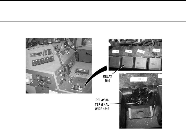
Turn vehicle ENGINE switch to OFF position (TM 9-2320-347-10). Turn battery
disconnect switch to OFF position (WP 0007). Remove HEMMIT relay R10
(TM 9-2320-325-14&P). Turn battery disconnect switch to ON position (WP 0007).
Start vehicle ENGINE (TM 9-2320-347-10). While an assistant puts and holds HIGH
IDLE switch to ON position (WP 0004), with a test lead set, check for 22 to 28 VDC from
wire 1516 (black) in HEMTT relay 86 terminal to a known good ground.
a.
If 22 to 28 VDC are present, replace relay R10 (TM 9-2320-325-14&P).
b.
If 22 to 28 VDC are not present, troubleshoot Engine High Idle Does
Not Operate (TM 9-2320-325-14&P).
0171-12

