DRAFT
TM 5-4210-249-13&P-2
0171
MALFUNCTION
TEST OR INSPECTION
CORRECTIVE ACTION
TFFT04517A
Step 17.
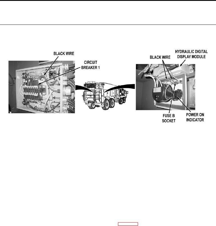
Check for continuity across black wire from circuit breaker 1 to hydraulic generator
digital display module fuse B socket.
If continuity is not present, replace hydraulic generator digital display cord
(WP 0361).
Step 18.
Check for continuity across black wire from hydraulic generator display module fuse B
socket to POWER ON indicator.
a.
If there is continuity, replace hydraulic generator digital display module
(WP 0585).
b.
If continuity is not present, replace black wire (TM 9-2320-325-14&P).
Step 19.
Put HIGH IDLE switch to OFF then ON position (WP 0004). Check if engine speed
increases to approximately 1,000 RPM, when HIGH IDLE switch is put to ON position.
If engine speed increases to approximately 1,000 RPM, adjust hydraulic
generator compensator (WP 0192).
Step 20.
Turn hydraulic generator off (WP 0021). Shut vehicle engine off (TM 9-2320-347-10).
Put ENGINE switch to ON position (TM 9-2320-347-10). Release vehicle brakes
(TM 9-2320-347-10). While an assistant pushes brake pedal, check if vehicle brake
lights operate (TM 9-2320-347-10).
If brake lights do not operate, troubleshoot brake lights (TM 9-2320-347-10).
0171-10

