TM 5-4210-233-14&P-2
6-35. IDLER GEARS - Continued
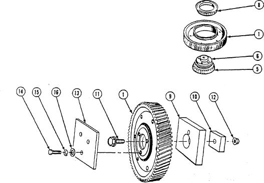
(11) Support outer bearing cone (5) and idler gear hub (6).
(12) Install idler gear assembly (1) onto idler gear hub (6).
CAUTION
Turn gear while installing bearing cone on idler gear hub to
prevent damage to bearing cups.
(13) Turn idler gear assembly (1) while pressing inner bearing cone (8), numbered side up, over hub (6).
(14) Hold hub (6) and turn gear assembly (1) to see it binding occurs.
NOTE
To check idler gear pre-load, do steps (15) through (25).
(15) Mount idler gear (1) in soft jaw vise.
(16) Mount two test fixture plates (9 and 10) on idler gear (1) with screw (11) and nut (12). Tighten to 80 to
90 Ib-ft (108 to 122 N.m).
(17) Mount test fixture plate (13) on idler gear (1) with three screws (14), lockwashers (15), and washers
(16). Tighten to 25 to 40 lb-ft (34 to 54 N.m).
(18) Place plate (1 0) in jaws of vise.
6-203

