 |
|||
|
|
|||
|
Page Title:
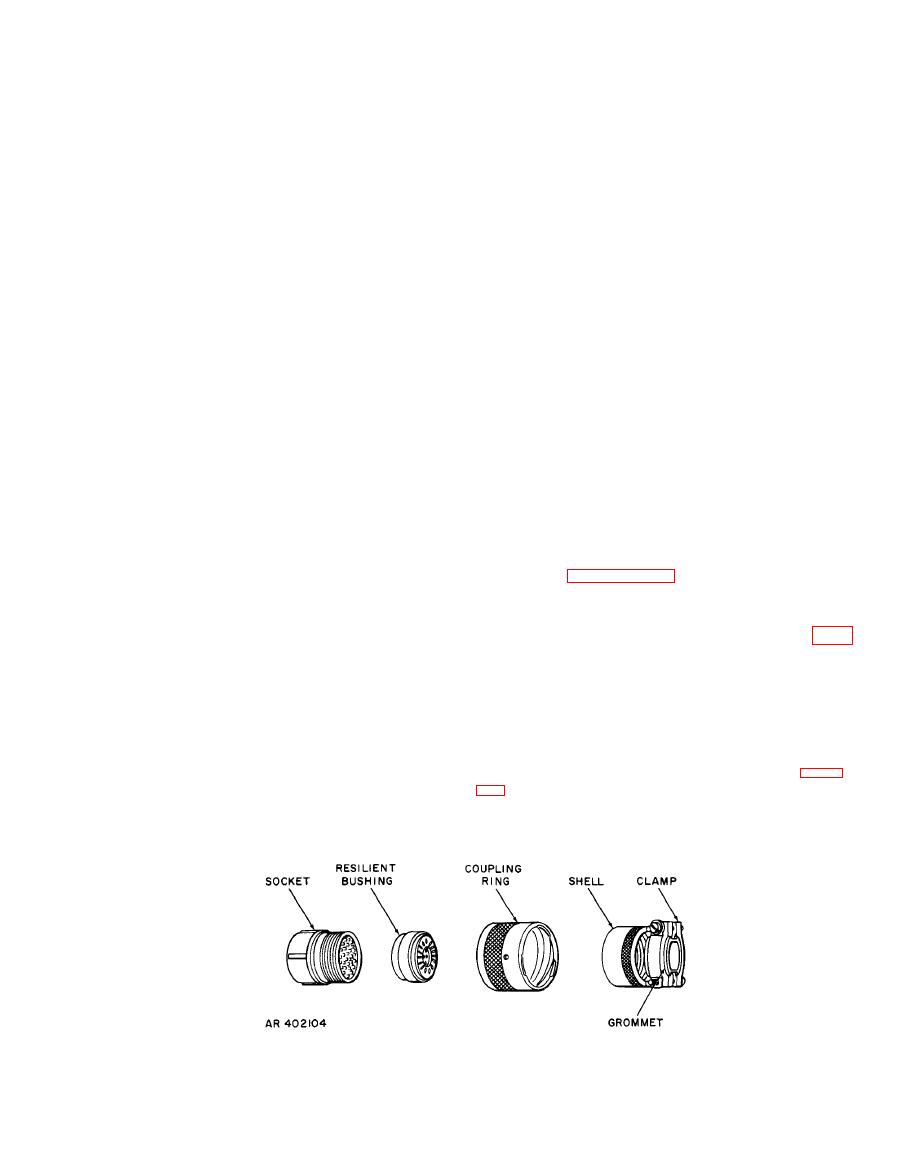
Figure 4-2. MS connector disassembly and assembly typical |
|
||
| ||||||||||
|
|
 TM 9-4931-363-14&P
(4) Do not use any shims (13) at this time. The
w i t h the LOD in the line of sight with a target of
opportunity at least 1000 meters away.
number used is determined in e below.
(5) When installing each T-1ock (5) and associated
(4) Mount the borescope in the boresight adapter
items (4) through (1), coat the threads of screw (1) with
and sight on the target. Loosen the C-clamp and center the
the same sealing compound as used for screw (36), as stated
reticle on the target by adjusting the position of the LOD.
Tighten C-clamp.
in step (1) above.
e. After assembly, check LOD adjustment as follows:
NOTE
(1) With rail clamp base assembly (9) locked in the
If an
adjustment must be made in step (5)
O-degree position and aligned approximately parallel to
below
and shimming was installed in step (1)
leveling base assembly (40), check the parallelism between
above,
insure that the shimming is not changed
the short axis of leveling base assembly (40) and rail clamp
during
the adjustment.
base assembly (9) as follows:
(5) Place the boresight in angle bracket (23) and view
(a) Use a pair of 4- to 6-inch calipers (dial or
the same target. The target should be centered on the
vernier type) to measure the distance between the top of
reticle within 3 roils. If not, loosen four screws (1 O)
rail clamp base assembly (9) and the bottom of leveling
attaching swivel plate (14) to swivel frame (19) and rotate
base assembly (40). Measure on each side of the LOD. Hold
swivel plate (14) to remove the error. Tighten screws (1 O)
the calipers in line with the center of the legs of swivel
and check that the target is centered on the reticle within 3
frame (19). Record the reading on each side of the LOD. If
roils. If the error still exceeds 3 roils, replace angle bracket
the two readings differ by more than 0.005 inch, loosen
(23).
four screws (10) and insert shim or shims (13) equal in
t h i c k n e s s to one-half the difference between the two
readings. Insert the shimming on screws (10) between
f. C h e c k t h e m a g n e t a l i g n m e n t a c c o r d i n g t o t h e
swivel frame (19) and swivel plate (14) on the side having
procedures of paragraph 4-25, linkage orientation device
the smallest reading.
magnet alignment.
(b) Tighten
screws
(10)
and
repeat
the
measurements.
B-4).
(2) Install the 7.62-mm borescope adapter from the
a. R e m o v e i t e m s ( 1 ) t h r o u g h ( 8 ) i n d i s a s s e m b l y
7.62-mm boresight kit (NSN 4933-00-930-1957) in one of
sequence. U n s o l d e r and mark leads where necessary.
the grooves of rail clamp base assembly (9). Insure that rail
Assemble in reverse disassembly sequence.
clamp base assembly (9) is locked in the 0-degree position.
(The grooves in rail clamp base assembly (9) and the line of
sight of angle bracket (23) are parallel.)
resilient bushing, and tag it. Assemble in reverse
(3) Use a C-clamp to mount the LOD on a suitable
disassembly sequence.
rigid mount, with leveling base assembly (40) down and
|
|
Privacy Statement - Press Release - Copyright Information. - Contact Us |