 |
|||
|
|
|||
|
Page Title:
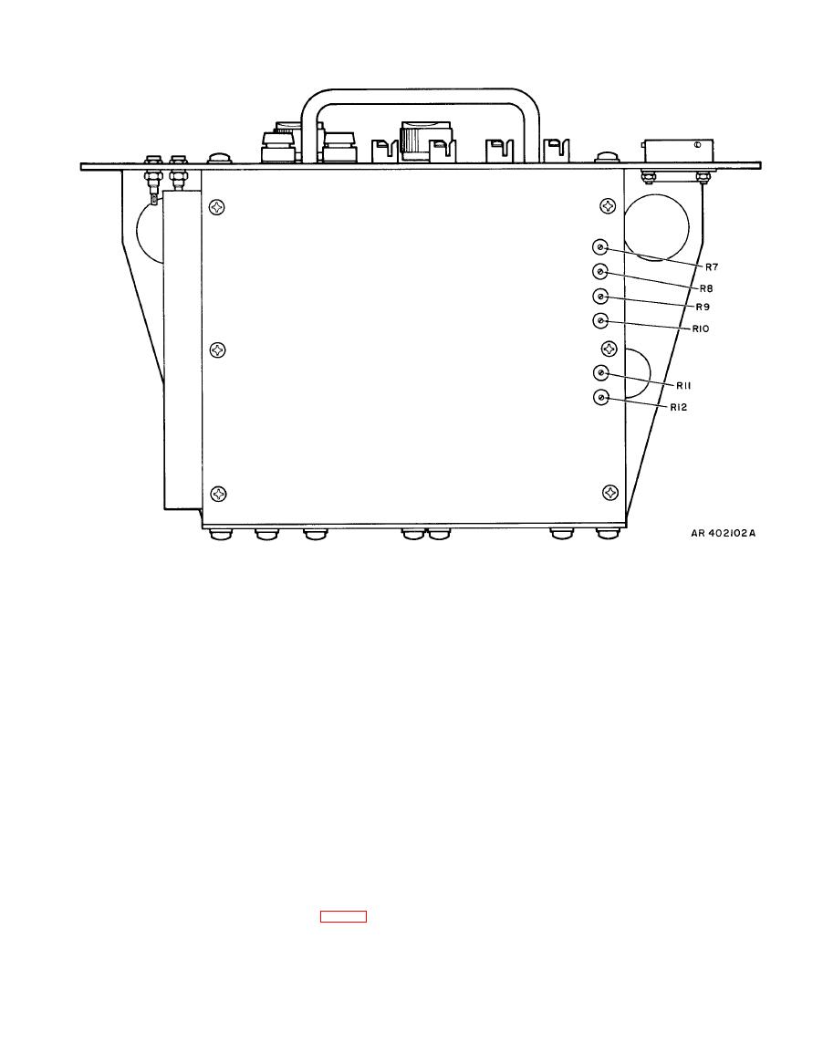
Figure 4-3. Parts locator view, adjustments |
|
||
| ||||||||||
|
|
 TM 9-4931-363-14&P
(2) Mount the borescope from the 7.62-mm
(2) Set the RSLVR SELECT switch to position R2,
boresight kit (NSN 4933-00-930-1957) in the borescope
press the FUNCTION INITIATE switch, and insure that the
angle bracket and sight on the target. Adjust the C-clamp to
multimeter reads 9.8 1 vrms and that the PHASE 180
center the target in the borescope.
indicator is on.
(3) Mount the boresight tool to the magnet of the
l. If either of the step k indications is out of tolerance,
LOD with the sighting tube below the LOD.
loosen the setscrew and adjust the resolver shaft until both
indicators are within tolerance. Tighten the setscrew. If the
voltage readings are within tolerance, but the PHASE 180
(4) Sight the target through the sighting tube of the
boresight tool. The target should be centered in the field of
indicator does not light when the FUNCTION INITIATE
view of the boresight tool simultaneously with centering in
switch is pressed, replace card A2.
the field of the borescope. If the target is not centered in
m. Install the test set chassis assembly in the container.
the field of the boresight tool, adjust the magnet.
(5) When magnet alignment is completed, remove the
borescope and the boresight tool, and dismount the LOD
by removing the C-clamp.
a. Performance Check.
b. Adjustment.
(1) Secure the LOD rail clamp base in the 0-degree
position. Use a C-clamp to mount the LOD (fig. 4-4) on a
suitable rigid mount, with leveling base assembly up, in the
(1) If alignment of the boresight tool does not
line of sight with a target of opportunity, that is, at least
coincide with that of the borescope, determine whether the
boresight tool is offset in azimuth or elevation, or both.
1000 meters away.
|
|
Privacy Statement - Press Release - Copyright Information. - Contact Us |