
DRAFT
TM 5-4210-249-13&P-4
FIELD LEVEL MAINTENANCE
HYDRAULIC GENERATOR RESERVOIR BOOST UNIT ASSEMBLY REPLACEMENT
INITIAL SETUP:
- - - - - - - - - - - - - - - - - - - - - - - - - - - - - - - - - - - - -
Tools and Special Tools
References
Tool Kit, General Mechanic's: Automotive
WP 0615, Fig. 178
(WP 0622, Item 27)
Equipment Conditions
Materials/Parts
Hydraulic reservoir drained (WP 0588)
Preformed Packing (1)
Hydraulic oil filter removed (WP 0589)
Preformed Packing (1)
Preformed Packing (1)
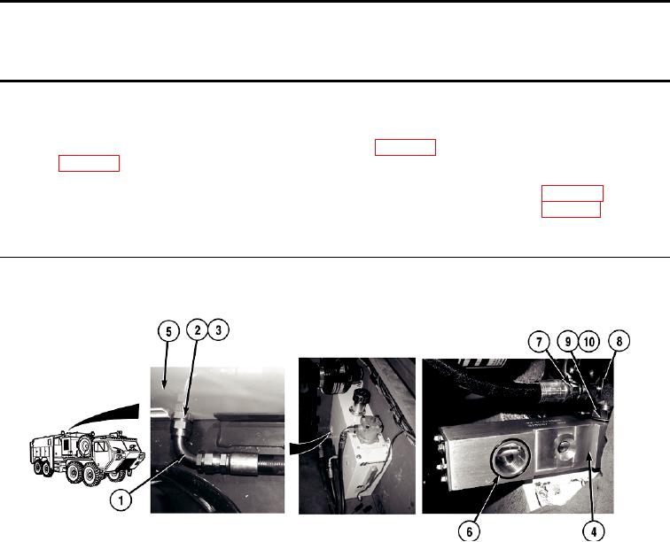
REMOVAL
TFFT00623
1.
Remove elbow (1) from fitting (2).
NOTE
Boost unit assembly is located inside the hydraulic reservoir and is removed through the
filter head opening.
2.
Remove fitting (2), preformed packing (3), and boost unit assembly (4) from hydraulic reservoir (5). Discard
preformed packing.
3.
Remove preformed packing (6) from boost unit assembly (4). Discard preformed packing.
4.
Remove hose (7) from elbow (8).
NOTE
Note position of elbow prior to removal to ensure proper installation.
5.
Remove elbow (8), washer (9), and preformed packing (10) from boost unit assembly (4). Discard preformed
packing.
END OF TASK
0593-1