DRAFT
TM 5-4210-249-13&P-3
FIELD LEVEL MAINTENANCE
POWER STEERING PUMP MODIFICATION
INITIAL SETUP:
- - - - - - - - - - - - - - - - - - - - - - - - - - - - - - - - - - - - -
Tools and Special Tools
Materials/Parts (continued)
Cap Set, Protective (WP 0622, Item 3)
Lockwasher (5)
Drain Pan (WP 0622, Item 9)
Gasket (1)
Tool Kit, General Mechanic's: Automotive
Preformed Packing (1)
(WP 0622, Item 27)
Preformed Packing (2)
Materials/Parts
References
Adhesive, Sealant (WP 0625, Item 5)
WP 0615, Fig. 115
Compound, Sealing (WP 0625, Item 17)
Equipment Conditions
Sealing Compound Loctite 592
Hydraulic reservoir drained
(WP 0625, Item 21)
(TM 9-2320-325-14&P)
Tags, Identification (WP 0625, Item 51)
Ties, Cable, Plastic (WP 0625, Item 58)
REMOVAL
TFFT04252
NOTE
The vehicle engine air compressor and steering pump have switched
positions (WP 0002). By switching positions, fittings, and rotor vane housing positions
have changed on steering pump.
Tag and mark hoses prior to removal to ensure proper installation.
Remove cable ties as required.
Position suitable drain pan under hoses to catch excess oil.
Cap and plug hoses upon removal.
1.
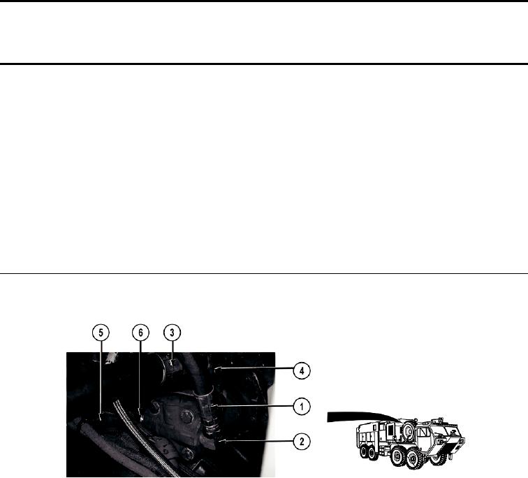
Remove hose (1) from elbow (2).
2.
Remove hose (3) from elbow (4).
3.
Remove hose 2301 (5) from elbow (6).
0535-1

