DRAFT
TM 5-4210-249-13&P-3
0485
- - - - - - - - - - - - - - - - - - - - - - - - - - - - - - - - - - - - -
TFFT0049A
NOTE
Support bracket holding discharge pipes must be removed with valve assembly to permit
clearance for discharge valve replacement.
Pipe and valve are replaced as an assembly.
4.
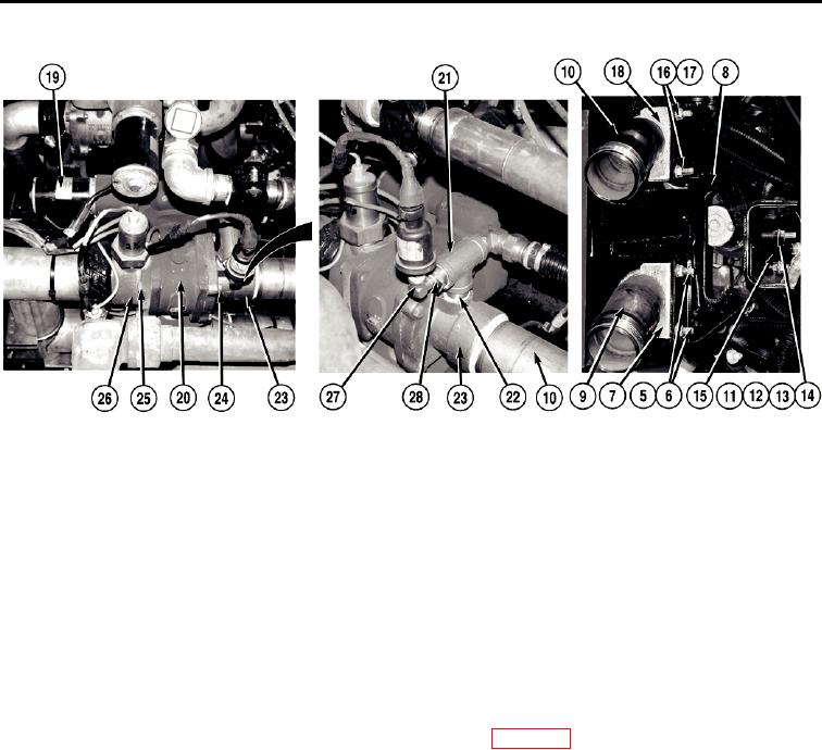
Remove two locknuts (5), U-bolt (6), and cradle (7) from bracket (8) and pipe (9). Discard locknuts.
5.
With the aid of an assistant, support pipe (10) and remove two nuts (11), lockwashers (12), four washers (13),
and two screws (14) from bracket (8) and channel bracket (15). Discard lockwashers.
6.
With the aid of an assistant, remove pipe (10) and bracket (8) from vehicle.
7.
Remove two locknuts (16), U-bolt (17), cradle (18), and pipe (10) from bracket (8). Discard locknuts.
8.
Remove electric motor and drive assembly (19) from valve (20) (WP 0388).
9.
Remove tee (21) and nipple (22) from adapter (23).
10. Remove pipe (10) from adapter (23).
NOTE
Note position of adapters on valve prior to replacement to ensure proper installation.
11. Remove four screws (24) and adapter (23) from valve (20).
12. Remove four screws (25) and adapter (26) from valve (20).
13. Remove elbow (27) from fitting (28).
14. Remove fitting (28), elbow (3), and nipple (22) from tee (21).
END OF TASK
0485-3

