DRAFT
TM 5-4210-249-13&P-2
FIELD LEVEL MAINTENANCE
PRIMER VALVE CABLE REPLACEMENT
INITIAL SETUP:
- - - - - - - - - - - - - - - - - - - - - - - - - - - - - - - - - - - - -
Tools and Special Tools
References
Tool Kit, General Mechanic's: Automotive
WP 0615, Fig. 41
(WP 0622, Item 27)
Equipment Conditions
Materials/Parts
Pump operator's panel manual primer handle
Ties, Cable, Plastic (WP 0625, Item 58)
removed (WP 0329)
Lockwasher (2)
Pump house panel A opened (WP 0539)
REMOVAL
TFFT01065
NOTE
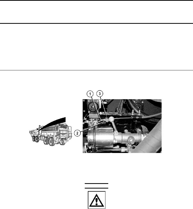
Both primer valve cables are removed the same way. Primer valve cable No.1 shown.
1.
Straighten cable wire (1).
- - - - - - - - - - - - - - - - - - - - - - - - - - - - - - - - - - - - -
WARNING
ICON 72
Care must be taken when removing cable wire from arm and bracket. Wire is under
tension and must be held until safely repositioned. Failure to comply may result in
injury to personnel.
NOTE
Note position of retainer on cable wire prior to removal to ensure proper installation.
2.
Loosen screw (2) and remove retainer (3) from cable wire (1).
0265-1

