DRAFT
TM 5-4210-249-13&P-1
0104
MALFUNCTION
TEST OR INSPECTION
CORRECTIVE ACTION
TFFT02889
NOTE
Voltage while performing Step 73 will switch from negative VDC to VDC when bumper
turret control is in oscillation. This is normal operation.
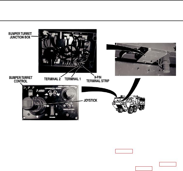
Step 73.
Turn battery disconnect switch to OFF position (WP 0007). Install bumper turret control
cover and tighten four screws. Remove bumper turret junction box cover (WP 0573).
Disconnect bumper turret motor power wire (red) from bumper turret junction box 9-pin
terminal strip (WP 0573). Turn battery disconnect switch to ON position (WP 0007).
Put bumper turret control oscillation switch to on position (WP 0004). Check for 22 to
28 VDC between bumper turret motor power wire (red) at bumper turret motor power
wire (black) at bumper turret junction box 9-pin terminal strip, terminal 1 to terminal 2.
If there is 22 to 28 VDC, go to Step 78.
0104-48

