DRAFT
TM 5-4210-249-13&P-1
OPERATOR MAINTENANCE
DESCRIPTION AND USE OF OPERATOR'S CONTROLS AND INDICATORS
CONTROLS AND INDICATORS INTRODUCTION
This section shows the location and describes the use of controls and indicators used to operate the M1142
firefighting systems. Refer to TM 9-2320-347-10 for all other controls and indicators.
Know location and proper use of every control and indicator before operating the vehicle. Use this section to learn
about each control and indicator to be used. Separate illustrations with keys are provided for the following group of
controls and indicators:
- - - - - - - - - - - - - - - - - - - - - - - - - - - - - - - - - - - - -
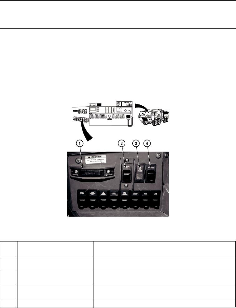
TFFT00026P
Figure 1.
Cab Instrument Panel - Upper Left.
- - - - - - - - - - - - - - - - - - - - - - - - - - - - - - - - - - - - -
Key
Control or Indicator
Function
Fig. 1
1
DO NOT MOVE APPARATUS
Indicator light illuminates whenever a compartment door is open or
WHEN LIGHT IS ON indicator
equipment (ladder) rack is down.
2
GENERATOR PTO Switch
Push up to engage generator PTO. Push down to disengage
generator PTO.
3
GENERATOR PTO ENGAGED
Indicator light illuminates when generator PTO is engaged.
Indicator Light
4
DECKLIGHT Switch
Push up to engage decklight. Push down to disengage decklight.

