DRAFT
TM 5-4210-249-13&P-1
0104
MALFUNCTION
TEST OR INSPECTION
CORRECTIVE ACTION
TFFT02884
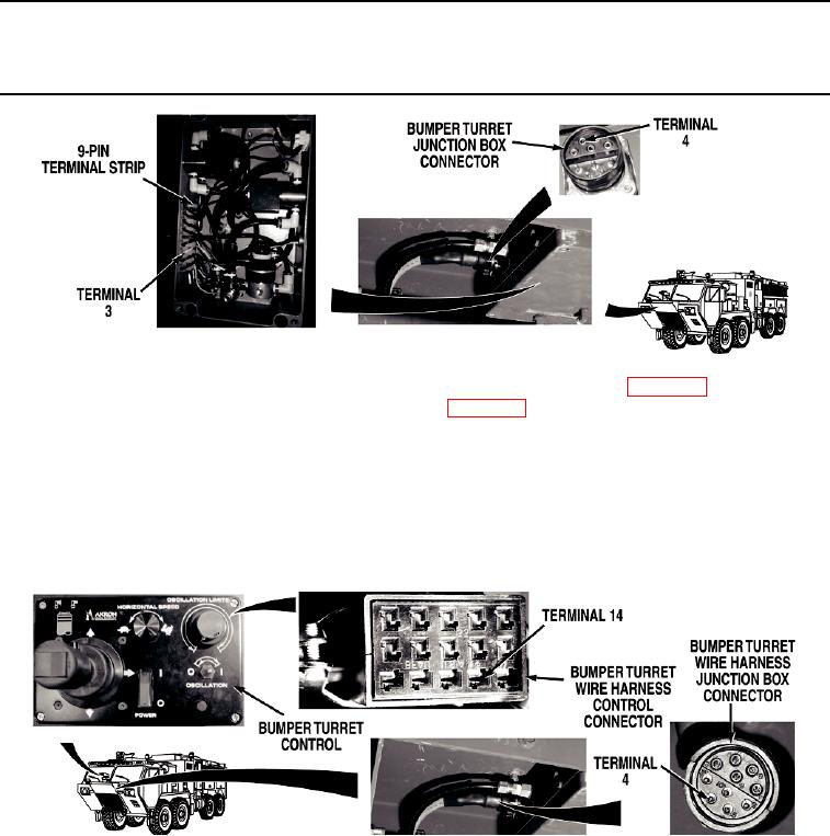
Step 67.
Put bumper turret control POWER switch to
(off) position (WP 0004). Turn battery
disconnect switch to OFF position (WP 0007). Disconnect bumper turret wire harness
bumper turret junction box connector. Check for continuity across bumper turret
junction box position sensor power wire (yellow) from bumper turret junction box
connector, terminal 4 to bumper turret junction box 9-pin terminal strip, terminal 3.
If there is no continuity, repair bumper turret junction box position sensor
power wire in bumper turret junction box wire harness if repairable
(TM 9-2320-325-14&P), or replace bumper turret junction box wire
harness (WP 0573).
TFFT02885
Step 68.
Remove cab instrument panel E (WP 0311). Disconnect bumper turret wire harness
bumper turret control connector. With a test lead set, check for continuity across
bumper turret wire harness position sensor power wire (yellow) from bumper turret wire
harness bumper turret control connector, terminal 14 to bumper turret wire harness
bumper turret junction box connector, terminal 4.
a.
If there is continuity, replace bumper turret control (WP 0570).
b.
If there is no continuity, repair bumper turret wire harness position
sensor power wire in bumper turret wire harness if repairable
(TM 9-2320-325-14&P), or replace bumper turret wire
harness (WP 0437).
0104-45

