DRAFT
TM 5-4210-249-13&P-1
0080
MALFUNCTION
TEST OR INSPECTION
CORRECTIVE ACTION
TFFT04436
Step 3.
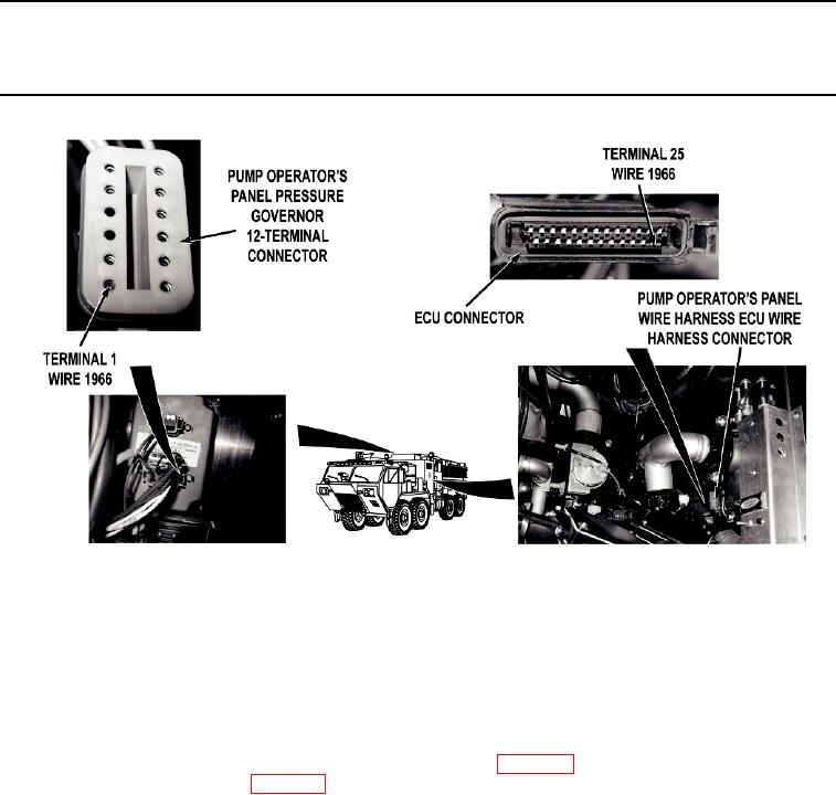
With a test lead set, check for continuity across wire 1966 from pump operator's panel
pressure governor 12-terminal connector, terminal 1 to ECU connector, terminal 25.
If continuity is not present, repair wire 1966 in pump operator's panel wire
harness if repairable (TM 9-2320-325-14&P), or replace pump operator's
panel wire harness (WP 0459).
Step 4.
Reconnect pump operator's panel wire harness ECU wire harness connector. Turn
battery disconnect switch to ON position (WP 0007). Start water pump
engine (WP 0022). With a test lead set, check for voltage fluctuation of 0 to 5 VDC at
wire 1966 from pump operator's panel pressure governor 12-terminal connector,
terminal 1 to a known good ground.
a.
If steady 5 VDC are present, replace pump operator's panel pressure
governor control panel (WP 0332).
b.
If steady 5 VDC are not present, replace water pump engine
ECU (WP 0226).
0080-3

