
DRAFT
TM 5-4210-249-13&P-1
0004
- - - - - - - - - - - - - - - - - - - - - - - - - - - - - - - - - - - - - -
TFFT00264P
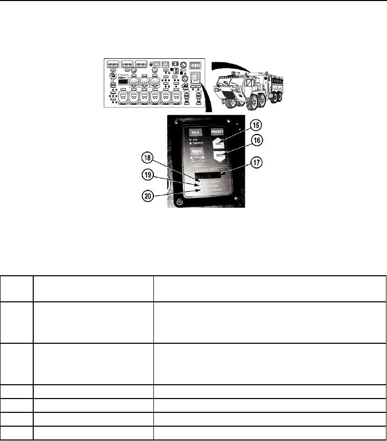
Figure 13.
Pump Operator's Panel - Upper Right (Sheet 3 of 3).
- - - - - - - - - - - - - - - - - - - - - - - - - - - - - - - - - - - - - -
Key
Control or Indicator
Function
Fig. 13
15
Increase (INC) Switch
When INC switch is pressed, INCREASE is displayed in
MESSAGE CENTER. Depressing INC switch increases water
pump engine RPM. When INC switch is released, current pump
engine RPM are maintained by pressure governor.
16
Decrease (DEC) Switch
When DEC switch is pressed DECREASE is displayed in
MESSAGE CENTER. Depressing DEC switch decreases water
pump engine RPM. When DEC switch is released, current water
pump engine RPM are maintained by pressure governor.
17
MESSAGE CENTER
Displays current information about pressure governor.
18
PUMP ENGAGED LED
Illuminates when water pump is engaged.
19
OKAY TO PUMP LED
Illuminates when it is ok to start pump operations.
20
THROTTLE READY LED
Illuminates when throttle is ready.
- - - - - - - - - - - - - - - - - - - - - - - - - - - - - - - - - - - - - - - - - - - - - - - - - - - - - -
0004-20