DRAFT
TM 5-4210-249-13&P-1
0004
- - - - - - - - - - - - - - - - - - - - - - - - - - - - - - - - - - - - - -
TFFT00489AP
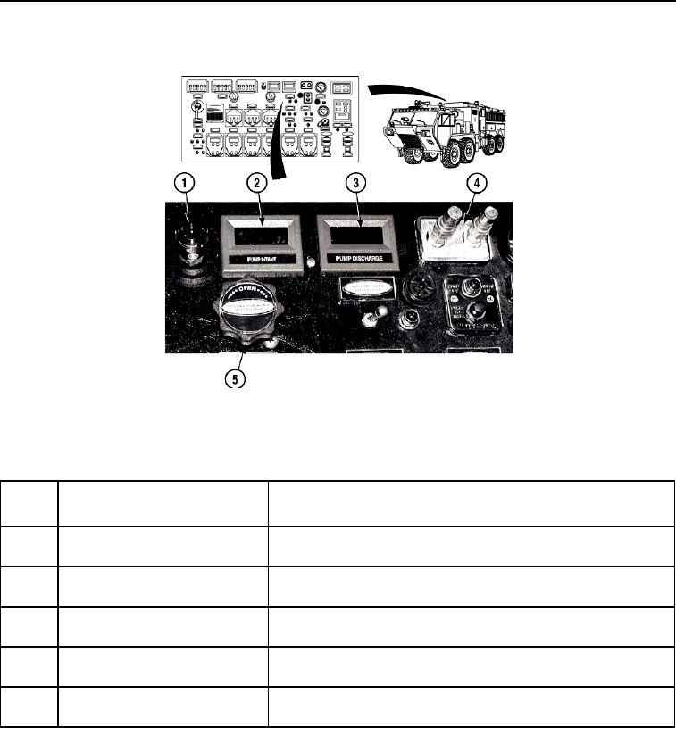
Figure 12.
Pump Operator's Panel - Upper Center (Sheet 1 of 2).
- - - - - - - - - - - - - - - - - - - - - - - - - - - - - - - - - - - - - -
Key
Control or Indicator
Function
Fig. 12
1
Air Flow Restrictor Indicator
Shows condition of water pump engine air cleaner filter. Indicator
window shows red when filter becomes clogged.
2
PUMP INTAKE Gauge
Indicates the vacuum and pressure present in the intake side of
the pump system in psi.
3
PUMP DISCHARGE Gauge
Indicates the pressure present in the discharge side of pump
system in psi.
4
Test Gauge Panel
Connections used for testing the accuracy of the water pump
performance.
5
PASSENGER AUXILIARY INLET
Turn counterclockwise to open bleeder valve. Turn clockwise to
BLEEDER Valve
close bleeder valve.
- - - - - - - - - - - - - - - - - - - - - - - - - - - - - - - - - - - - - - - - - - - - - - - - - - - - - -

