
TM 5-4210-233-14&P-2
6-55. GEAR UNIT AND MAIN SHAFT ASSEMBLY - Continued
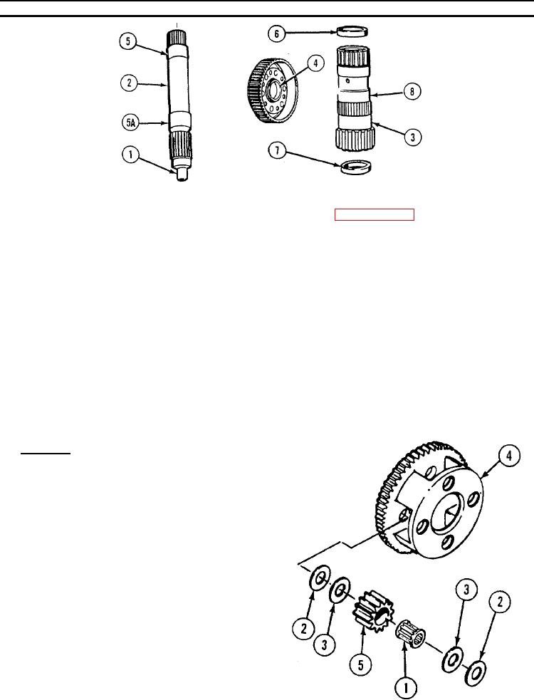
NOTE
Bearing surface measurement will be used in paragraph 6-58 to
find output shaft bushing clearance.
(4)
Measure and note diameter of bearing surface (1) of main shaft (2).
(5)
Measure diameter of front carrier bearing surface (3).
(6)
Measure inside diameter of bushing (4).
(7) If bushing (4) to front carrier bearing surface (3) clearance is greater than 0.0072 in. (0.18 mm),
replace bushing.
(8)
Measure diameter of bearing surfaces (5 and 5A) on main shaft (2).
(9)
Measure inside diameter of bushings (6 and 7) in sun gear shaft (8).
(10) If clearance between bushings (6 and 7) and bearing surfaces (5 and 5A) is more than 0.0064-in.
(0.16 mm), remove bushings.
d. Assembly.
NOTE
Front, center, and rear carrier assemblies
are assembled the same way. Assembly
of center carrier is shown.
(1)
Lubricate roller bearings (1), bronze thrust
washers (2), and steel thrust washers (3) with
lubricating oil.
(2)
Position center carrier assembly (4) in press
with front end up.
(3)
Install roller bearings (1) in pinion (5).
(4)
Install steel thrust washer (3) at each end of
pinion (5).
(5)
Install bronze thrust washer (2) on each steel
thrust washer (3).
6-306