
DRAFT
TM 5-4210-249-13&P-4
FIELD LEVEL MAINTENANCE
HYDRAULIC GENERATOR OIL COOLER FAN REPLACEMENT
INITIAL SETUP:
- - - - - - - - - - - - - - - - - - - - - - - - - - - - - - - - - - - - -
Tools and Special Tools
References
Tool Kit, General Mechanic's: Automotive
WP 0615, Fig. 8
(WP 0622, Item 27)
Equipment Conditions
Materials/Parts
Wheels chocked (TM 9-2320-347-10)
Lockwasher (4)
Batteries disconnected (TM 9-2320-325-14&P)
REMOVAL
- - - - - - - - - - - - - - - - - - - - - - - - - - - - - - - - - - - - -
TFFT4076
NOTE
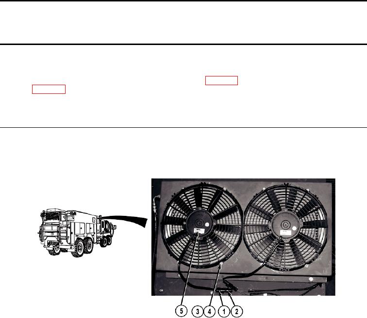
Both hydraulic generator oil cooler fans are removed the same way. Front fan shown.
1.
Disconnect fan connector (1) from crew cab wire harness connector (2).
2.
Remove four nuts (3), lockwashers (4), and hydraulic generator oil cooler fan (5) from vehicle. Discard
END OF TASK
0587-1