DRAFT
TM 5-4210-249-13&P-1
0122
MALFUNCTION
TEST OR INSPECTION
CORRECTIVE ACTION
TFFT03625
Step 11.
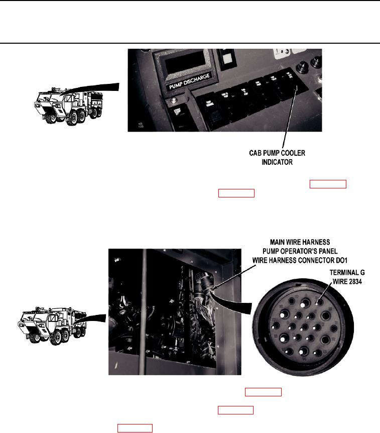
Put pump operator's panel PUMP COOLER switch to OFF position (WP 0004). Put cab
PUMP COOLER switch to on position (WP 0004) and release. Check if cab PUMP
COOLER OPEN indicator illuminates.
If cab PUMP COOLER OPEN indicator does not illuminate, go to Step 14.
TFFT03626
Step 12.
Turn battery disconnect switch to OFF position (WP 0007). Remove driver side crew
cab access panel (WP 0499). Remove pump house panel Q (WP 0540). Put cab
PUMP COOLER switch to off position (WP 0004). Disconnect main wire harness pump
operator's panel wire harness connector DO1. Turn battery disconnect switch to ON
position (WP 0007). With a test lead set, check for 22 to 28 VDC between main wire
harness wire 2834 (red) at main wire harness pump operator's panel wire harness
connector DO1, terminal G and a known good ground.
If 22 to 28 VDC are present, repair wire 2834 in pump operator's panel wire
harness if repairable (TM 9-2320-325-14&P), or replace pump operator's
panel wire harness (WP 0459).
0122-11

