
DRAFT
TM 5-4210-249-13&P-1
0110
MALFUNCTION
TEST OR INSPECTION
CORRECTIVE ACTION
TFFT02654
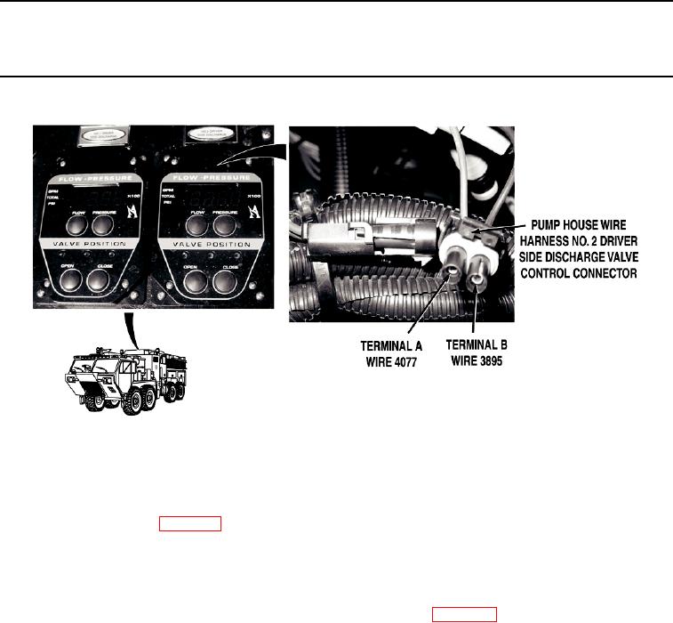
Step 18.
Install circuit breaker P10 (WP 0412). Open pump operator's panel
housing (WP 0325). Disconnect pump house wire harness NO. 2 DRIVER SIDE
DISCHARGE valve control connector. Turn battery disconnect switch to ON position
(WP 0007). Check for 22 to 28 VDC between pump operator's panel wire harness wire
4077 (blue) at NO. 2 DRIVER SIDE DISCHARGE valve control connector, terminal A
and a known good ground.
If 22 to 28 VDC are not present, go to Step 20.
Step 19.
Turn battery disconnect switch to OFF position (WP 0007). With a test lead set, check
for continuity across wire 3895 (black) from pump operator's panel NO. 2 DRIVER SIDE
DISCHARGE valve control connector, terminal B and a known good ground.
a.
If there is continuity, replace No. 2 DRIVER SIDE DISCHARGE valve
control (WP 0417).
b.
If there is no continuity, repair wire 3895 in pump operator's panel wire
harness if repairable (TM 9-2320-325-14&P), or replace pump
operator's panel wire harness (WP 0459).
0110-15