TM 5-4210-233-14&P-2
6-6. FIRE PUMP - Continued
NOTE
This O-ring (40A) serves only to hold the locking arm (39) on the pivot pin if the assembly is in a right
side up position.
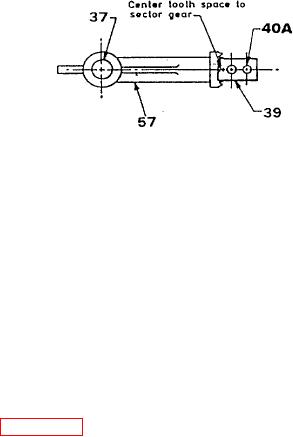
(37) Install the locking arm (39) on pivot pin (40) and mesh with teeth on the sector gear (57). Proper
meshing of these is when the pin end of the locking arm (39) is in line with the sector gear (57) and the
center tooth space in the sector gear (57) is centered with the pivot pin (40).
(38) Install shifter shoe on the pin on the locking arm (39).
NOTE
Shifter shoe (39) can be installed with face with counterbore at hole either up or down.
(39) Install adjusting screws
(103) in the mid-section
and adjust these screws
to that locking arm (39)
is rotatable slightly bless
than 90 each direction
from a center position
with the sector gear (57).
(40) Slide the shift collar (35) into engagement with the shoes on the shift fork (36). The 3/16" (4.8 mm)x
45 (chamfered) pointed (tapered) end of the collar to face towards the drive shaft end of the case.
(41) Take the drive shaft (34) and housing assembly (11) and install it into the half bore in the mid-section
(15) of case. Make sure tachometer drive outlet is correctly orientated. Engage the teeth at the end
of the drive sprocket (24) with those in the shift collar (35). Line up holes in housing (11) with holes in
the case and install cap screws (13) and lockwashers (14) and tighten finger tight only.
(42) Support the mid-section (15) and drive shaft (34) assembly on suitable blockings so the flange that
cap (42) will bolt to is up.
(43) Make sure face of flanges that meet on the mid-section (15) and cap (42) are clean and free of nicks
and burrs.
(44) Install dowels (63) in top flange of the mid-section (15).
(45) Apply light coat of sealant (Item 35, Appendix E) to face of top flange of the mid-section (15).
(46) Position previously assembled cap (42) and driven shaft (67) on dowels (63) in the top flange of the
mid-section (15) and tap down into contact with mid-section (15).
(47) Install screws (62 and 63A) with lockwashers (62A and 63B) and tighten evenly.
6-23

