 |
|||
|
|
|||
|
|
|||
| ||||||||||
|
|
 TM 5-4210-224-14 & P
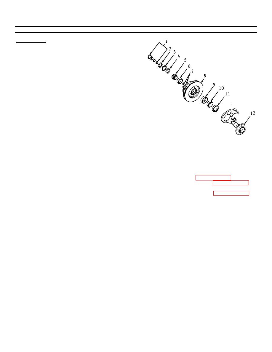
4-234. WHEEL BEARING ADJUSTMENT. (Continued)
ADJUSTMENT
NOTE
The proper functioning of the front
suspension cannot be maintained
unless the front wheel bearings are
correctly adjusted.
The cones
must be a slip fit on the spindle
and the inside diameter of the
cones must be lubricated to insure
the cones will creep. The adjusting
nut must have a free-running fit on
the spindle threads.
a. Torque the adjusting nut (4) to 50 ft-lbs (60 N.m)
while rotating the hub/rotor in order to seat the
b. Back off the adjusting nut (4) and retighten.
c. Torque the adjusting nut to 50 ft-lbs (60 N.m)
while rotating the wheel.
d. Back off the adjusting nut (4) enough to free the
f. Torque the lock nut (2) to 160 ft-lbs (217 N.m)
bearing.
minimum.
e. Adjust the ring (3) and lock nut (2).
g. Measure the endplay in the hub/ rotor assembly.
It should be set between 0.001 to 0.010 inch
NOTE
(0.025 to 0.254mm).
The tang on the inside diameter of
h. Install the locking hub assembly (1).
the ring must pass onto the slot on
i. Install the caliper (paragraph 4-218).
the spindle (12). The hole in the
j. Install the wheel following paragraph 4-203 and
ring must align with the pin on the
torque the stud nuts to 140 ft-lbs (190 N.m).
lock nut (2). Move the adjustment
k. Install manual locking hub (paragraph 4-253).
nut (4) to align the pin.
4-328
|
|
Privacy Statement - Press Release - Copyright Information. - Contact Us |
