 |
|||
|
|
|||
|
Page Title:
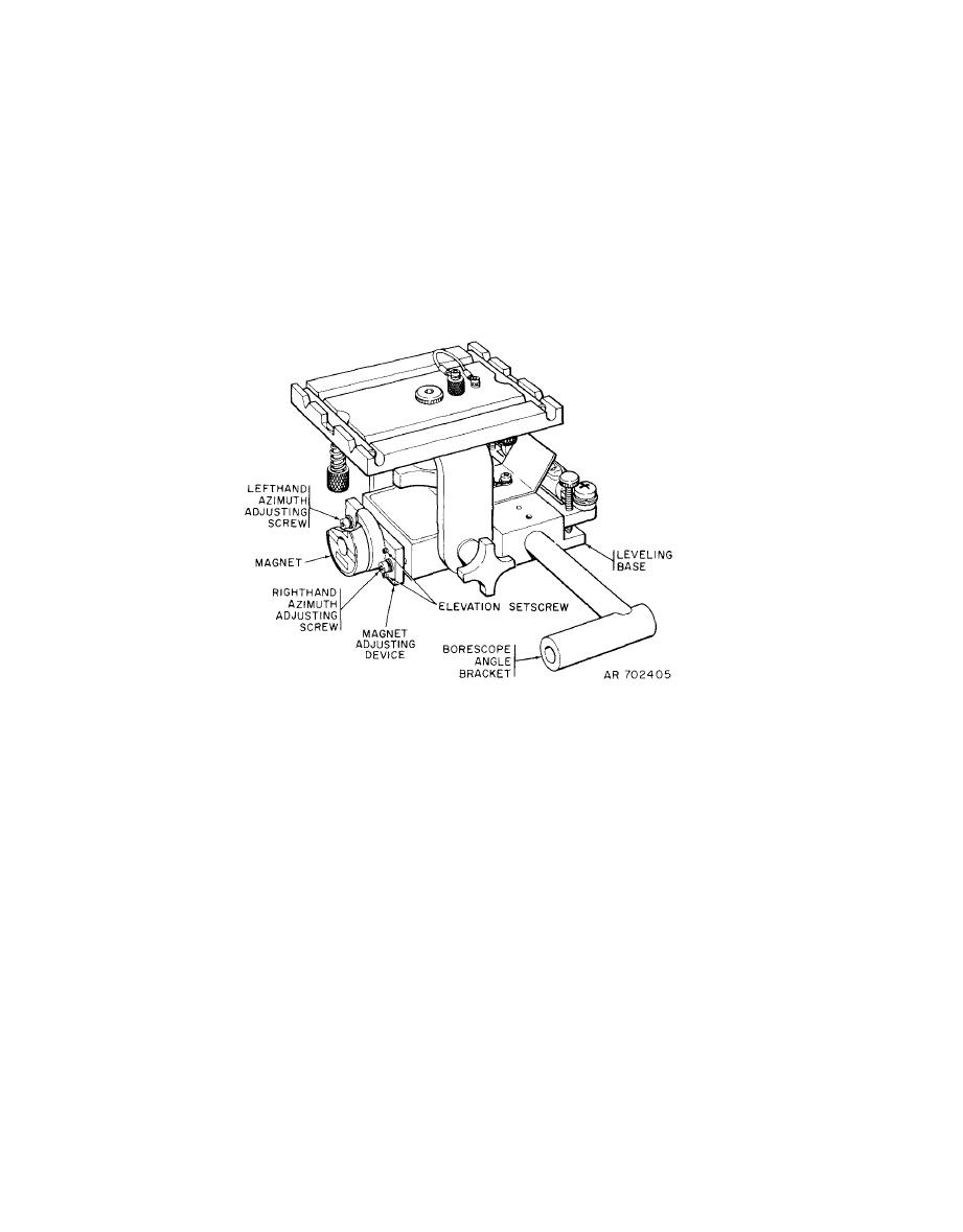
Figure 4-4. Linkage orientation device magnet alignment |
|
||
| ||||||||||
|
|
 TM 9-4931-363-14&P
brought into elevation alignment. Use a standard 5/64-inch
(2) Slightly loosen the righthand azimuth adjusting
hexhead wrench.
screw, using a standard 9/64 hexhead wrench.
(5) Azimuth adjusting screws and elevation setscrews
(3) If azimuth alignment is required, loosen one
are interacting, and the above adjustments may have to be
azimuth adjusting screw and tighten the other until the
repeated to accomplish final alignments. All adjusting
magnet is brought into azimuth alignment.
s c r e w s may be securely tightened when alignment is
completed.
(6) Remove the borescope and the boresight tool,
(4) If elevation adjustment is required, loosen one
and dismount LOD by removing the C-clamp.
elevation setscrew and tighten the other until the magnet is
|
|
Privacy Statement - Press Release - Copyright Information. - Contact Us |
