 |
|||
|
|
|||
|
Page Title:
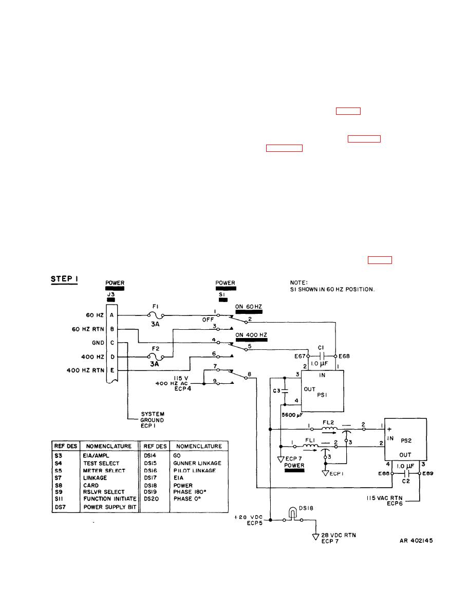
Figure 2-2. Test set self-test functional diagram (sheat 1 of 4) |
|
||
| ||||||||||
|
|
 TM 9-4931-363-14&P
signals to a dc level. The negative dc level at the base of Q1
(2) If an in-phase signal (waveform D) is inserted for
keeps the transistor turned off. The negative dc level is
detection at XA2-41, the signal is connected to the
inverting input of AR1. A low-amplitude signal is amplified
applied to the inverting input at AR3-2. The output signal
at AR3-6 (waveform I) is, effectively, a positive dc level,
2.35 times and the output signal at AR1-6 (waveform E) is
which turns on Q3, applying a ground at XA2-37 to light
limited by 5.1-volt zener diodes CR1 and CR2. Thus, a
PHASE 0 indicator DS20 (fig. 2-2, step 7).
low-amplitude signal will retain its original waveshape,
while a signal exceeding 10.2 volts peak to peak will be
limited at that value. The limited and inverted signal is
applied through 200K resistor R4 to the inverting input at
AR2-2. The theoretical output at AR2-6 (waveform F) will
8 in figure 2-2. Contact 3 and wiper 1 of S3-L connect 10
be an inverted square wave of the same amplitude as the
volts ac, phase angle 180 degrees, through the route
input. The limited and inverted square wave from AR1-6 is
described above to XA2-41. The out-of-phase signal
also connected through R6 and R7 to the noninverting
(waveform J) is limited and inverted by AR1 and appears as
input at AR2-3. Since the input impedance 100K and the
an in-phase signal at AR1-6 (waveform K). The theoretical
load resistance is 200K, the gain of the noninverting input
output of the signal at AR2-2 (inverting input) is an
out-of-phase square wave (waveform L). The theoretical
is 2. The theoretical output at AR2-6 (waveform G)
output of the signal at AR2-3 (noninverting input) is an
consists of amplified negative-going pulses only, since the
positive-going pulses are grounded by the action of the
in-phase amplified square wave (waveform M). The
composite output of the two signals is a series of positive
chopper. The composite output of the two signals at AR2-6
(waveform H) is a series of negative pulses, the amplitude of
pulses (waveform N) that are, effectively, a dc level. The
positive dc level turns on Q1, applying a ground at XA2-35
which is the difference between the two waveforms. The
faltering of R7, C2, and C3, and of C1 and R5, changes the
to light PHASE 180 indicator DS19 (fig. 2-2, step 8).
|
|
Privacy Statement - Press Release - Copyright Information. - Contact Us |
