 |
|||
|
|
|||
|
|
|||
| ||||||||||
|
|
 TM 9-4931-363-14&P
THEORY OF OPERATION
Section I. GENERAL
2-1. Scope.
a. This chapter provides the theory of operation of the
test set and the theory of tests for the HSS items under
test. Thus, the theory discussions are a composite of test set
theory and item-under-test theory. The following material
provides an understanding of the theory:
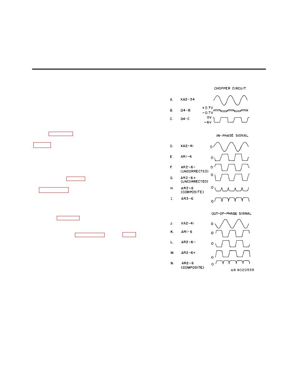
(1) Figure 2-1 is a timing diagram for the phase
detector circuit on circuit card A2. Functional diagrams
connections for each step of each test. The functional
diagram layouts follow the same order as the steps of the
troubleshooting tables in TM 9-1270-212-14&P.
(2) The schematic diagrams of applicable test cables
W3, W4, and W5 (figs. 2-13 through 2-15) are located at the
end of this chapter. The schematic diagram for test cable
W2 (foldout FO-1) is located at the end of this manual.
NOTE
The schematic diagram of the helmet boresight
cable is figure 2-16.
(3) The schematic diagram of the test set and two
printed circuit cards (foldouts FO-2 through FO-4) are
located at the end of this manual.
b. The theory discussions use test set connector and pin
designations. For example, logic card A10 from the EIA
used in XM128 and logic card A15 from the EIA used in
XM136 are each tested in test set connector J8; therefore,
all connections to and from a logic card in the theory carry
the test set J8 designation.
|
|
Privacy Statement - Press Release - Copyright Information. - Contact Us |