|
| |
TM 9-254
8-7.
Oscilloscope Probes - Continued
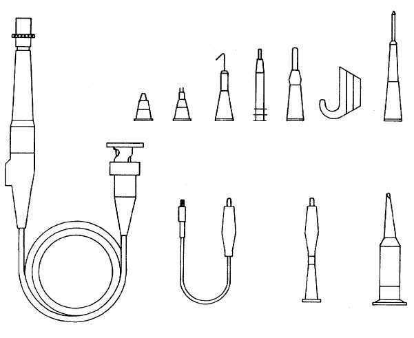
Figure 8-15. Oscilloscope Probes
(1)
Touch the probe tip to the center calibrator output jack (9, fig. 8-8) and adjust oscilloscope to display
several cycles of the signal.
(2)
Loosen the locking sleeve (fig. 8-16) and turn the probe body and tip assembly until the correct
waveform is displayed on the screen.
(3)
After the correct adjustment has been made, hold the probe body (fig. 8-16) and tighten the locking
sleeve.
8-22
|