 |
|||
|
|
|||
|
|
|||
| ||||||||||
|
|
 TM 9-1240-375-34&P
0098 00
4.
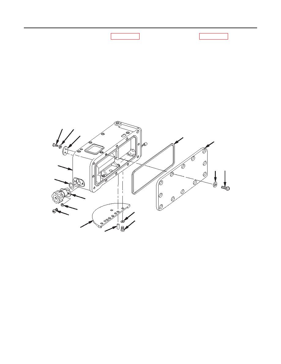
Apply a light coat of grease (item 15, WP 0152 00) to new O-ring (6) (item 21, WP 0141 00) and install
on knob assembly (7).
5.
Turn knob assembly (7) clockwise until it stops.
NOTE
Correction counter should read ON or between R-95 and R-99.
6.
Install knob assembly (7) and be sure that the shaft of knob assembly engages coupling pin of
correction counter.
7.
Turn knob assembly (7) counterclockwise until it stops. The corners of the correction counter should
read L-95 to L-99. If it does not, adjust the knob assembly accordingly.
18
16
17
10
13
2
14
15
6
7
5
9
8
3
4
1
1 fc 6 2 3
M137 Counter Box Assembly
0098 00-5
|
|
Privacy Statement - Press Release - Copyright Information. - Contact Us |