 |
|||
|
|
|||
|
|
|||
| ||||||||||
|
|
 TM 9-1240-375-34&P
0098 00
ASSEMBLY - Continued
16
18
17
10
13
2
15
14
11
6
12
7
9
8
1 fc 6 2 4
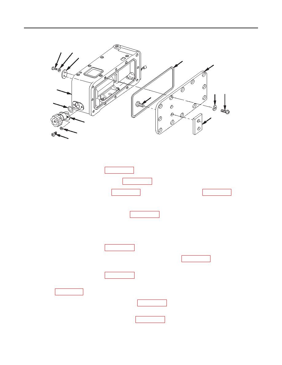
M137A2/M137A3 Counter Box Assembly
8.
Apply sealing compound (item 13, WP 0152 00) to threads of two machine screws (8).
9.
Install two new lockwashers (9) (item 19, WP 0141 00) and two machine screws (8). Tighten screws.
10.
Apply a light coat of grease (item 15, WP 0152 00) to new gasket (10) (item 10, WP 0141 00).
11.
Install new gasket (10) into counter box assembly (2).
12.
If removed, apply sealing compound (item 13, WP 0152 00) to threads of two machine screws (11)
(M137A2/M137A3 only).
13.
If removed, install spacer (12) on counter housing cover (13) and secure with two machine screws (11).
Countersink machine screws (M137A2/M137A3 only).
14.
Apply sealing compound (item 13, WP 0152 00) to threads of 12 machine screws (14).
15.
Install counter housing cover (13), 12 new lockwashers (15) (item 12, WP 0141 00), and 12 machine
screws (14).
16.
Apply sealing compound (item 13, WP 0152 00) to threads of two externally relieved screws (16).
17.
Place access cover (17) on counter box assembly (2) and secure in place with two new lockwashers (18)
(item 19, WP 0141 00) and two externally relieved screws (16).
18.
Apply a light coat of sealing compound (item 13, WP 0152 00) around edge of optical instrument
window (19) and install.
19.
Apply a light coat of sealing compound (item 13, WP 0152 00) to threads of two machine screws (20).
20.
Install window retaining plate (21) and two machine screws (20).
0098 00-6
|
|
Privacy Statement - Press Release - Copyright Information. - Contact Us |