|
| |
TM 750–116
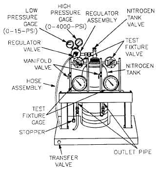
b. Setup for Two Stage Fixture (fig. 2–2).
Figure 2–2 Setup for Two–Stage Fixture,
PN 8565556
(1) Place a tank of dry nitrogen in a vertical position
in the back of the fixture so that the tank is lodged in the
structural steel “V” formation of the fixture and secure with
the strap and clamping screw arrangement provided.
(2) Secure regulator assembly to the tank. Make cer-
tain pressure regulator valve is turned counterclockwise
(CCW) to off. Open nitrogen tank valve (CCW) until max-
imum tank pressure is registered on the high pressure gage.
NOTE
If pressure indicated is less than 100 psi, obtain
and use a replacement tank.
(3) Connect hose assembly to regulator assembly.
Open manifold valve.
At no time should the pressure be permitted
to exceed 15 psi. Pressure greater than 15 psi
could damage the unit.
(4) Open transfer valve by pulling it to the outermost
position.
(5) Close test fixture valve(s) and ensure low pressure
gage indicates 0 psi.
(6) Open pressure regulator valve clockwise (CW)
until low pressure gage indicates 15 psi.
(7) Open test fixture valve(s) until test fixture gage(s)
indicate(s) proper pressure.
(8) Close manifold valve(s) and check pressure read-
ing on test fixture gage(s) .
(9) Remove stopper(s) from outlet pipe(s). Open
manifold valve(s) and check the pressure on test fixture
gage(s). Adjust fixture valve(s) if necessary.
(10) Close manifold valve(s) and attach feeder tube(s)
to outlet pipe(s).
(11) For bleed down procedures, refer to para 2-3.b.
2-3. BLEED DOWN OF PURGING AND
CHARGING EQUIPMENT (fig. 2-1 and
2 - 2 ).
DO NOT REMOVE REGULATOR ASSEM-
BLY, ADAPTER, OR HOSE BEFORE
FIRST PERFORMING ENTIRE BLEED
DOWN PROCEDURE. INJURY COULD
RESULT FROM SUDDEN RELEASE OF
HIGH PRESSURE GAS.
a. Bleed Down for Single Stage Fixture (fig.
2–1).
(1) Close pressure regulator valve counterclockwise
(CCW).
(2) Close tank valve clockwise (CW).
(3) Slowly open pressure regulator valve (CW) until
low pressure gage and high pressure gage both indicate
zero.
(4) Close pressure regulator valve (CCW).
Pressure regulator valve should be left in the
closed position when not in use. Leaving
valve in the open position could damage
regulator diaphragm.
b. Bleed Down for Two Stage Fixture (fig. 2-2).
(1) Close pressure regulator valve and test fixture
valve(s) counterclockwise (CCW).
(2) Close tank valve clockwise (CW).
(3) Open transfer valve by pulling it to the outermost
position.
(4) Rotate pressure regulator valve CW until low pres-
sure gage indicates 15 psi.
(5) With manifold valve(s) open, slowly rotate test
fixture valve(s) CW until low pressure gage, high pressure
gage and test fixture gage(s) indicate zero.
(6) Close pressure regulator valve and test fixture
valve(s) CCW.
2-2
|