|
| |
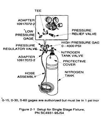
Figure 2-1.
TM 750-116
CHAPTER 2
GENERAL PROCEDURES
2-1. SCOPE. This chapter describes genera!
procedures for the setup of purging and charging
equipment time cycles.
2-2. SETUP OF PURGING AND CHARGING
EQUIPMENT, (figs. 2-1 and 2-2).
a. Setup for Single Stage Fixture(fig. 2-1)
(1) Obtain a tank of water pumped dry nitrogen and
remove threaded protective cover from the outlet of the
tank. Open tank valve momentarily to rid valve seat of
any foreign material.
(1.1) Remove the adapter from the regulator
install tee into the regulator. Install valve relief into
tee in the 3 o’clock position. install the adapter into
tee in the 6 o’clock position.
DO NOT DROP TANK OF COMPRESSED
NITROGEN GAS. WHEN USING IN CONFINED
AREAS, USE EXTREME CARE;
GAS COULD CAUSE ASPHYXIATION.
(2) Securely attach regulator to tank valve using ap-
propriate adapter supplied with purging kit if
necessary.
(3) Securely attach hose assembly to the adapter.
NOTE
When using regulator 11729749, adapter
10917072-2 is required to connect hose assembly to
low pressure to low pressure port of regulator.
(4) Close pressure regulator valve
counterclockwise (CCW) to the extreme closed
position.
(5) Open the nitrogen tank valve (CCW) slowly until
the maximum tank pressure is registered on the high
pressure gage.
NOTE
If pressure indicated is less than 100 psi, obtain
and use replacement tank.
(6) SIowly open pressure regulator valve clockwise
(CCW) until approximately 5 psi is registered on the low
pressure gage. Check for and eliminate any
interference; close pressure regulator valve (CCW).
(7) For bleed down procedures, refer to para 2-3a.
Change
1
2-1
|


