DRAFT
TM 5-4210-249-13&P-2
0145
TFFT04454
Step 7.
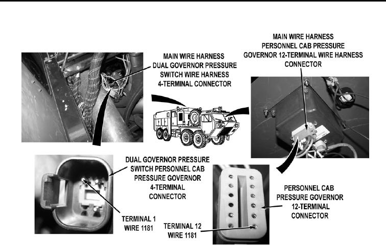
Turn water pump engine off (WP 0022). Turn battery disconnect switch to OFF
position (WP 0007). Open pump operator's panel housing (WP 0325). Disconnect
main wire harness dual governor pressure switch wire harness 4-terminal connector.
Remove personnel cab instrument panel E (WP 0311). Disconnect main wire harness
personnel cab pressure governor 12-terminal wire harness connector. With a test lead
set, check for continuity across wire 1181 from personnel cab pressure governor
12-terminal connector, terminal 12 to dual governor pressure switch personnel cab
pressure governor 4-terminal connector, terminal 1.
a.
If continuity is present, replace dual governor pressure
switch (WP 0386).
b.
If continuity is not present, repair wire 1182 in main wire harness if
repairable (TM 9-2320-325-14&P), or replace main wire
harness (WP 0455).
END OF TASK
FOLLOW-ON MAINTENANCE
Remove wheel chocks (TM 9-2320-347-10)
END OF TASK
END OF WORK PACKAGE
0145-6

