DRAFT
TM 5-4210-249-13&P-1
0112
MALFUNCTION
TEST OR INSPECTION
CORRECTIVE ACTION
TFFT02680
Step 12.
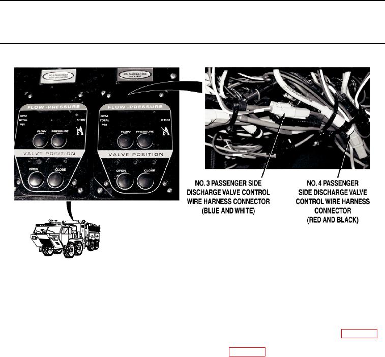
Open pump operator's panel housing (WP 0325). Connect No. 4 passenger side
discharge valve control wire harness connector to No. 4 passenger side discharge
valve motor. Disconnect No. 3 driver side discharge valve control wire harness
connector from NO. 3 DRIVER SIDE DISCHARGE valve control. Connect No. 4
passenger side discharge valve control wire harness connector to NO. 3 DRIVER SIDE
DISCHARGE valve control. Turn battery disconnect switch to ON position (WP 0007).
While an assistant pushes pump operator's panel NO. 3 DRIVER SIDE DISCHARGE
valve control OPEN and CLOSE buttons (WP 0004), check if No. 4 passenger side
discharge valve operates.
a.
If No. 4 passenger side discharge valve operates, reconnect valve
control wire harness connectors to original positions and replace NO. 4
PASSENGER SIDE DISCHARGE valve control (WP 0417).
b.
If No. 4 passenger side discharge valve does not operate, reconnect
valve control wire harness connectors to original positions and replace
No. 4 passenger side discharge valve motor (WP 0388).
0112-12

