
DRAFT
TM 5-4210-249-13&P-1
0112
MALFUNCTION
TEST OR INSPECTION
CORRECTIVE ACTION
TFFT02678
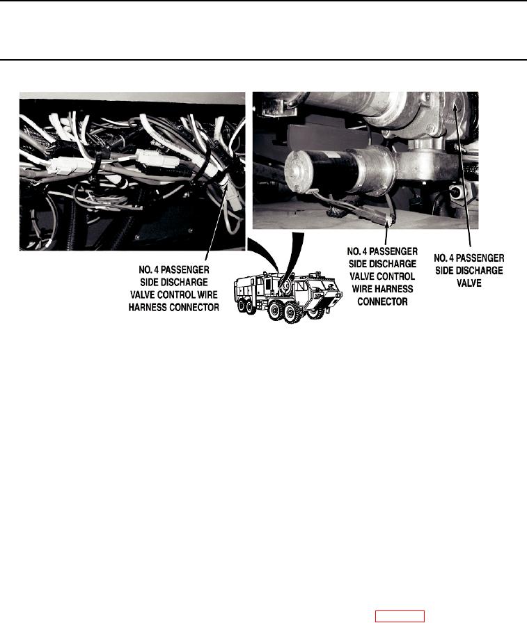
Step 9.
Open pump operator's panel housing (WP 0325). Check No. 4 passenger side
discharge valve control wire harness at NO. 4 PASSENGER SIDE DISCHARGE valve
control and No. 4 passenger side discharge valve motor for loose connections.
If No. 4 passenger side discharge valve control wire harness connectors are
loose, reconnect loose connectors (WP 0453).
NOTE
Engine may have to be running to provide enough power to operate valve control. Valve
will operate with less voltage, but only yellow indicator light will register on valve control.
Do not engage water pump engine during this procedure. Valve operations can be
checked without water pump operation.
Valve motor operation can be checked by noting vibration of valve assembly, or by
observing rotation of 7/16 in. hex at end of valve drive assembly worm gearshaft.
Do not remove cap from NO. 4 PASSENGER SIDE DISCHARGE. Water may be
released from system when valve is operated.
Step 10.
While an assistant pushes pump operator's panel NO. 4 PASSENGER SIDE
DISCHARGE valve control OPEN and CLOSE buttons (WP 0004), check if NO. 4
PASSENGER SIDE DISCHARGE valve control yellow indicator illuminates and No. 4
passenger side discharge valve motor operates.
If indicator illuminates and valve motor operates, replace No. 4 passenger
side discharge valve drive assembly (WP 0388).
0112-10