
DRAFT
TM 5-4210-249-13&P-1
0109
MALFUNCTION
TEST OR INSPECTION
CORRECTIVE ACTION
TFFT02697
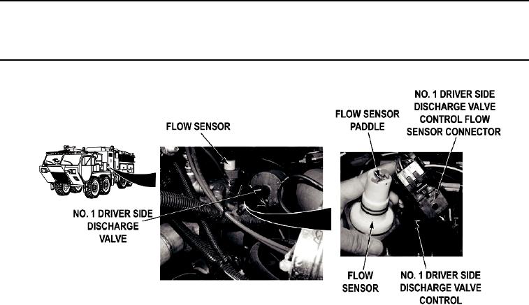
Step 16.
Disconnect No. 1 driver side discharge flow sensor (WP 0390) and connect it directly to
NO. 1 DRIVER SIDE DISCHARGE valve control (removing flow sensor wire harness
from circuit). While an assistant spins flow sensor paddle wheel, check if a flow reading
is displayed when the flow sensor paddle is spinning.
a.
If a flow reading is displayed when flow sensor paddle is spinning,
repair flow sensor wire harness if repairable (TM 9-2320-325-14&P), or
replace No. 1 driver side discharge flow sensor wire
harness (WP 0451).
b.
If a flow reading is not displayed when flow sensor paddle is spinning,
replace No. 1 driver side discharge flow sensor (WP 0390).
0109-11